

Ring structure for fixing mobile terminal on finger
A mobile terminal and finger technology, applied in the field of ring structure components, can solve the problems of poor versatility and inability to be widely promoted and used, and achieve the effects of strong versatility, free fingers, and convenient use
- Summary
- Abstract
- Description
- Claims
- Application Information
AI Technical Summary
Problems solved by technology
Method used
Image

Examples
Embodiment 1
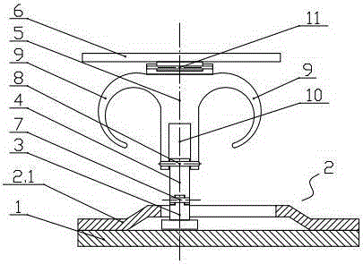
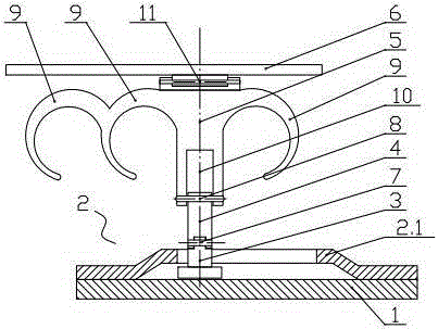
[0046] Such as figure 1 , figure 2 and image 3 As shown, the ring structure used to fix the mobile terminal on the finger of the present invention mainly includes a base plate 1, a sliding assembly 2, a ⊥-shaped rotating column 3, a middle piece connector 4, a ring fastener 5 and a supporting ornament 6.
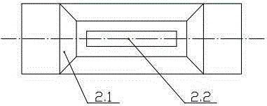
[0047] The above-mentioned sliding assembly 2 is installed on the base plate 1 . The sliding assembly 2 is a cover plate 2.1 with an upper convex portion, the periphery of the cover plate is fixed on the base plate, and a slide groove 2.2 is opened on the upper convex portion of the cover plate, and the ⊥-shaped rotating column is installed on the Inside the chute, and can slide left and right along the chute.
[0048] The above-mentioned ⊥-type rotating 3-column is installed on the sliding assembly, and can freely rotate along its central axis, that is, it can rotate along its central axis. The upper end of the intermediate connector 4 and the ⊥-shaped rotating column...
Embodiment 2
[0053] Such as Figure 4 and Figure 5 As shown, the ring structure used to fix the mobile terminal on the finger of the present invention mainly includes a base plate 1, a sliding assembly 2, a ⊥-shaped rotating column 3, a middle piece connector 4, a ring fastener 5 and a supporting ornament 6.
[0054] The above-mentioned sliding assembly 2 is installed on the base plate 1 . The slide assembly 2 is a slide bar 2.3 and a slide block 2.4, the slide bar is fixed on the substrate 1 through the supports 2.5 at both ends thereof, the slide block 2.4 is installed on the slide bar 2.3, and the slide block can be moved along The slide bar slides left and right, the upper side of the slider is provided with a concave slot, and the lower part of the ⊥-shaped rotating column 3 is snapped into the concave slot.
[0055] The above-mentioned ⊥-type rotating 3-column is installed on the sliding assembly, and can freely rotate along its central axis, that is, it can rotate along its centr...
Embodiment 3
[0060] Such as Figure 6 and Figure 7 As shown, the ring structure used to fix the mobile terminal on the finger of the present invention mainly includes a base plate 1, a sliding assembly 2, a ⊥-shaped rotating column 3, a middle piece connector 4, a ring fastener 5 and a supporting ornament 6.
[0061] The above-mentioned sliding assembly 2 is installed on the base plate 1 . The sliding assembly 2 is a zipper tape 2.6 and a slider 2.7, the periphery of the zipper tape 2.6 is fixed on the substrate 1, the slider 2.7 is installed on the two chain teeth of the zipper tape 2.6, and the slider can be moved along the The two chain tooth belts slide left and right, the upper side of the slider 2.7 is provided with a concave card slot, and the lower part of the ⊥-shaped rotating column 3 is clamped in the concave card slot.
[0062] The above-mentioned ⊥-type rotating 3-column is installed on the sliding assembly, and can freely rotate along its central axis, that is, it can rota...
PUM
 Abstract
Description
Claims
Application Information