Method for manufacturing filter element

A filter element and filter plate technology, which is applied in separation methods, dispersed particle filtration, chemical instruments and methods, etc., can solve the problems that cannot simply ensure the sealing continuity of filter elements, reduce the risk of bad positioning, and reduce circulation Effect on time and cost, reduction of scrap quantity and number of manufacturing steps

Active Publication Date: 2017-05-24
NOVARES FRANCE
View PDF8 Cites 0 Cited by
  • Summary
  • Abstract
  • Description
  • Claims
  • Application Information

AI Technical Summary

Problems solved by technology

[0009] The combination of non-woven media can also be arranged in the form of two thin strips placed on the lateral ends of the pleats of the filter plate, but this solution cannot simply ensure a seal over the entire outer contour of the filter element continuity

Method used


Image

  • Method for manufacturing filter element
  • Method for manufacturing filter element
  • Method for manufacturing filter element

Examples


Embodiment Construction

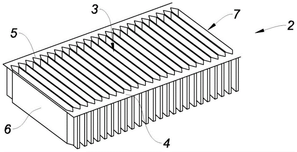
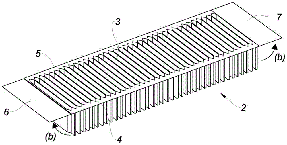
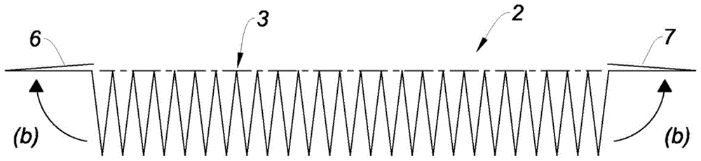
[0046] figure 1 To 6 show the manufacturing method of the filter element 1. Such as figure 1 As shown, the method includes a first step a), which consists in providing a filter plate 2 composed of a filter medium layer of, for example, a polyester elastic non-woven material. The synthetic material particularly includes a fiber whose core is a polyester material and whose sheath is a copolyester material, and the melting point of the sheath is much lower than the melting point of the core. This layer is pleatedly folded to present a set of parallel folds extending transversely between the first and second longitudinal edges 4,5. Usually, this layer is formed in advance by anchoring, and the longitudinal ends of the folds 3 are glued or welded (joined) in pairs and shaped with two tailless screws to form the first and second longitudinal ends 4, 5. Then, the layer is kept flat by providing a longitudinal connection, such as an adhesive tape or a thin tape at the top of the fold ...


PUM


Abstract

It comprises the steps consisting of: a) Providing a filtering panel (2) having a plurality of parallel folds (3) extending between a first planar longitudinal edge and a second planar longitudinal edge (5), the filtering panel (2) comprising, at the longitudinal ends of same, a first end fold (6) and a second end fold (7), b) Raising and holding the first end fold (6) and the second end fold (7) in a plane substantially parallel to the planes of the longitudinal edges (5), and c) Fixing a first sealing strip (8) on the first longitudinal edge, on a first portion (9) of the first end fold (6) and on a first portion (11) of the second end fold (7), and d) Fixing a second sealing strip (12) to the second longitudinal edge (5), on a second portion (13) of the first end fold (6) and on a second portion (14) of the second end fold (7). The invention also concerns a filtering element (1) that can be obtained by means of said method of production.

Description

Technical field [0001] The invention relates to a method for manufacturing a filter element, which is an air filter (engine or cab) for a motor vehicle. [0002] The invention also relates to a filter element, which is an air filter for a motor vehicle obtainable by the filtering method. Background technique [0003] Most of the filter elements available on the market are made of paper or synthetic materials and are pleated to increase the filter area achieved. These filter elements are provided with a coupling that ensures the sealability between the filter element and its reservoir (for example, a groove closed by a cover for an engine air filter), thereby ensuring that the filter element is commonly referred to as the "dirty air side". There is a strict separation between the volume of filtered air and the volume containing filtered air commonly referred to as the "clean air side". [0004] The combination used can have different compositions, such as thermoplastic resin or poly...

Claims


Application Information

Patent Timeline
Patent Type & Authority Patents(China)
IPC IPC(8): B01D46/00B01D46/10B01D46/52
CPCB01D46/0001B01D46/10B01D46/521
Inventor 珍-皮埃尔·巴赞菲力浦·皮诺伊曼纽尔·扬多什
Owner NOVARES FRANCE
Why Eureka
Try Eureka