Moisture removal device for steam turbine
A moisture and steam technology, applied in stators, engine components, machines/engines, etc., can solve the problems of decreased moisture removal efficiency and inability to remove water film flow, etc., and achieve the effects of improving moisture removal efficiency, inhibiting corrosion, and realizing life
- Summary
- Abstract
- Description
- Claims
- Application Information
AI Technical Summary
Problems solved by technology
Method used
Image
Examples
Embodiment approach 1
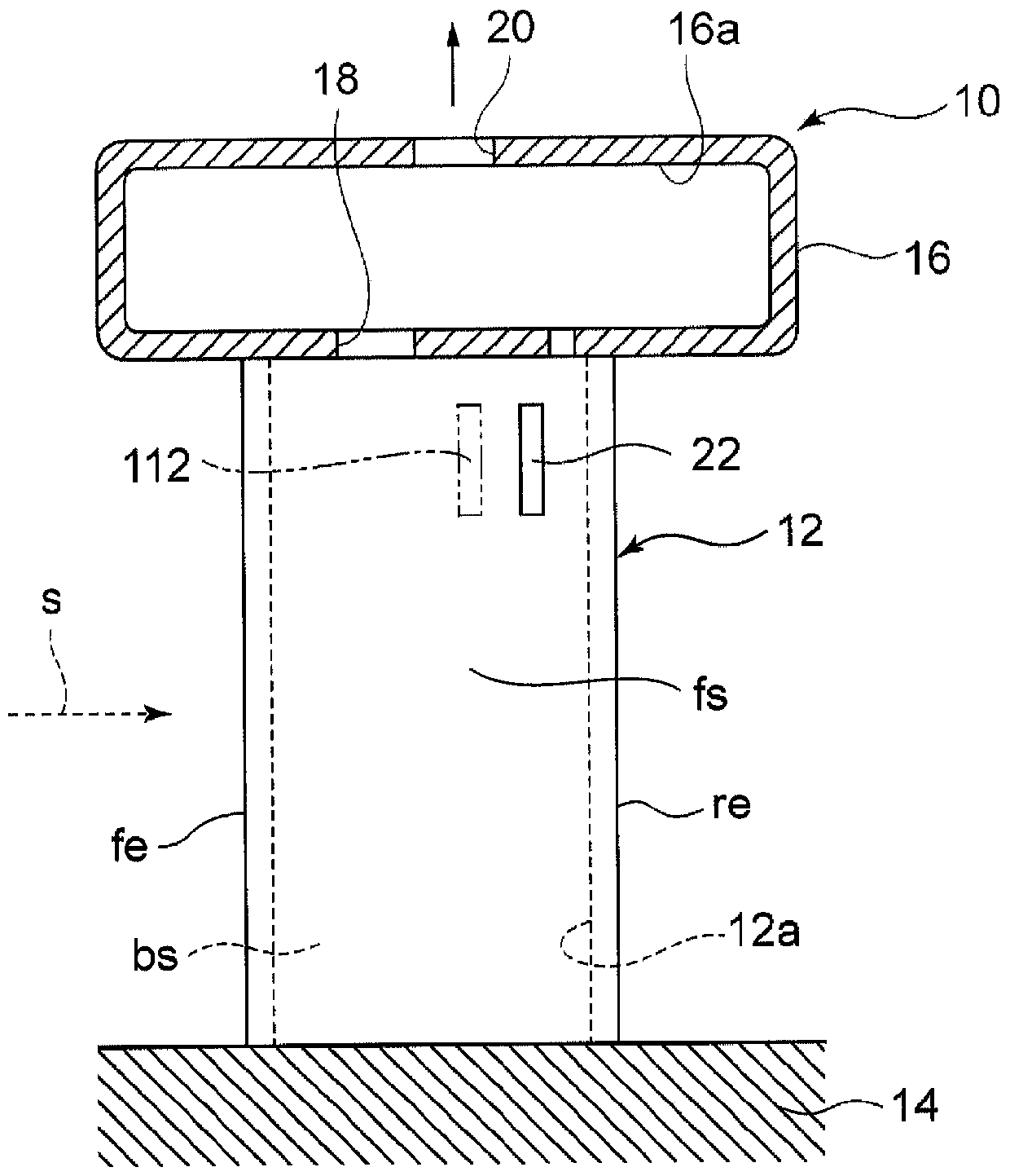
[0057] Next, pass Figure 1 ~ Figure 4 A water removal device according to a first embodiment of the present invention will be described. exist figure 1 Among them, the stator blade 12 is provided in the wet steam flow path of the steam turbine. The hub portion of the stator blade 12 is connected to the diaphragm 14 , and the tip portion is connected to the support ring 16 .
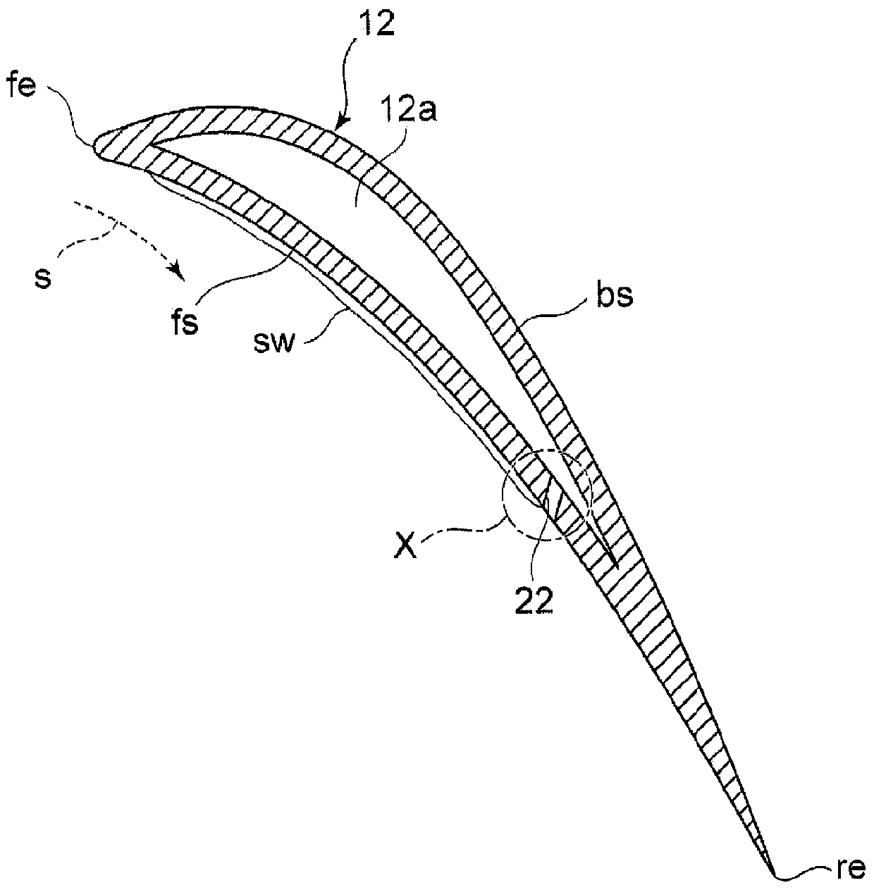
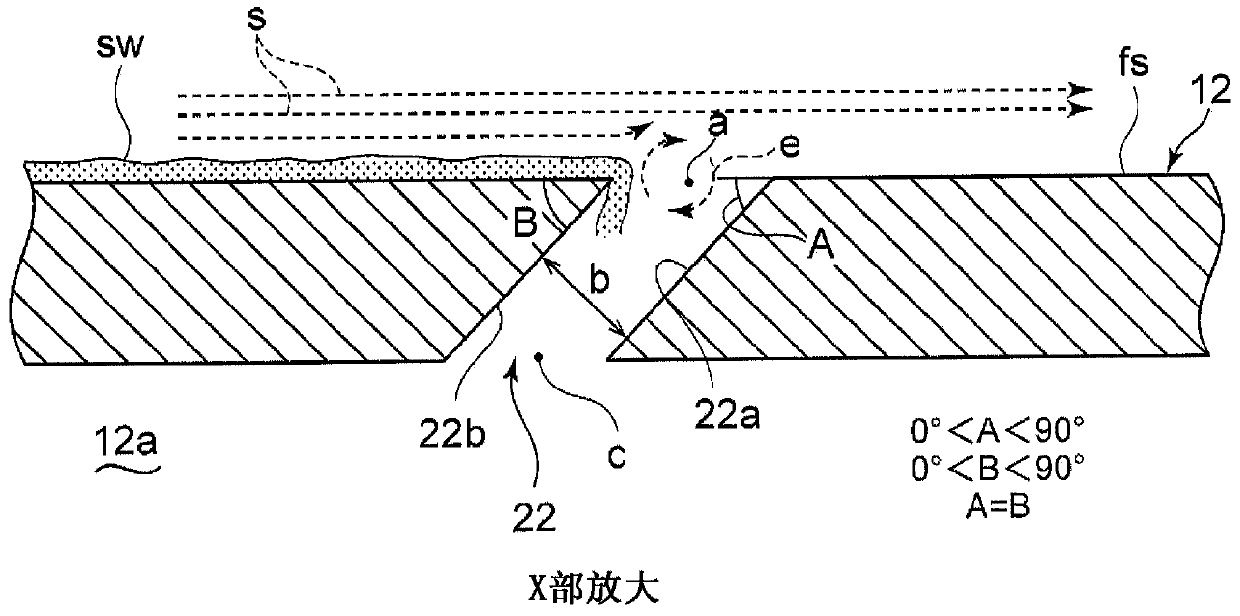
[0058] exist figure 2 in, with Figure 15 In the illustrated stator blade 100 similarly, the stator blade leading edge fe is arranged on the upstream side in the flow direction of the wet steam flow s with respect to the wet steam flow s, and the stator blade trailing edge re is arranged on the downstream side. Furthermore, the stator blade belly surface fs is arranged obliquely with respect to the wet steam flow s so as to face the wet steam flow s. Moisture contained in the humid steam flow s becomes water droplets and adheres to the ventral surface fs of the stator blade and the back surface of...
Embodiment approach 2
[0073] Next, based on Figure 6 A second embodiment of the present invention will be described. The location and orientation of the slit hole 30 in this embodiment with respect to the abdomen surface fs of the stator blade are the same as those of the slit hole 22 in the first embodiment. The stator blade trailing edge side wall surface 30a and the stator blade leading edge side wall surface 30b of the slit hole 30 have linear cross-sectional shapes, and the inclination angle A of the stator blade trailing edge side wall surface 30a relative to the leading edge side reference plane of the stator blade web surface fs, and the inclination angle B of the leading edge side wall surface 30b of the stator blade relative to the leading edge side reference plane of the stator blade ventral surface fs, the former forms an acute angle and the latter forms an obtuse angle (0°<A<90°, 90°<B<180° , A+B=180°).
[0074] That is, the cross section of the slit hole 30 is formed bilaterally sy...
Embodiment approach 3
[0077] Next, based on Figure 7 , the third embodiment of the present invention will be described. The arrangement position and direction of the slit hole 40 in this embodiment are the same as those of the slit hole 22 in the first embodiment. Compared with the slit hole 22 of the first embodiment, the cross-sectional shape of the slit hole 40 is a shape in which the inlet side region 40 b of the leading edge side wall surface of the stator blade is notched.
[0078] That is, the inclination angle A of the trailing edge side wall surface 40a of the stator blade with respect to the leading edge side reference plane of the stator blade belly surface fs is set as an acute angle (0°<A<90°), and the inlet side region 40b of the stator blade leading edge side wall surface is relatively The inclination angle B of the reference plane on the leading edge side of the blade belly surface fs is set as an obtuse angle (90°<B<180°), and the inclination of the outlet side area 40c of the le...
PUM
 Abstract
Description
Claims
Application Information
 - R&D
- Intellectual Property
- Life Sciences
- Materials
- Tech Scout
- Unparalleled Data Quality
- Higher Quality Content
- 60% Fewer Hallucinations
Browse by: Latest US Patents, China's latest patents, Technical Efficacy Thesaurus, Application Domain, Technology Topic, Popular Technical Reports.
© 2025 PatSnap. All rights reserved.Legal|Privacy policy|Modern Slavery Act Transparency Statement|Sitemap|About US| Contact US: help@patsnap.com


