Automatic screw-in device for screws

A screw and automatic technology, applied in metal processing, metal processing equipment, manufacturing tools, etc., can solve problems such as unstable posture, screw stuck, screw deflection, etc., and achieve the effect of improving the range

Active Publication Date: 2016-02-17
吉田建材(苏州)有限公司
View PDF7 Cites 2 Cited by
  • Summary
  • Abstract
  • Description
  • Claims
  • Application Information

AI Technical Summary

Problems solved by technology

[0003] However, in the pipeline blowing method, because the screw will be stuck or even turned over in the pipeline, it is impossible to supply screws with very short threads
In the vacuum adsorption mode, the vacuum suction rod structure is generally set on the elastic mechanism on the batch nozzle, which has limitations, so the screw screwing stroke cannot be too deep
In addition, in the vacuum suction method, the bottom of the screw is not support

Method used


Image

  • Automatic screw-in device for screws
  • Automatic screw-in device for screws
  • Automatic screw-in device for screws

Examples


Example Embodiment

[0032] Hereinafter, preferred embodiments of the present invention will be described in detail with reference to the drawings. Here, in the description of the drawings, the same reference numerals are assigned to the same or corresponding elements, and overlapping descriptions are omitted.

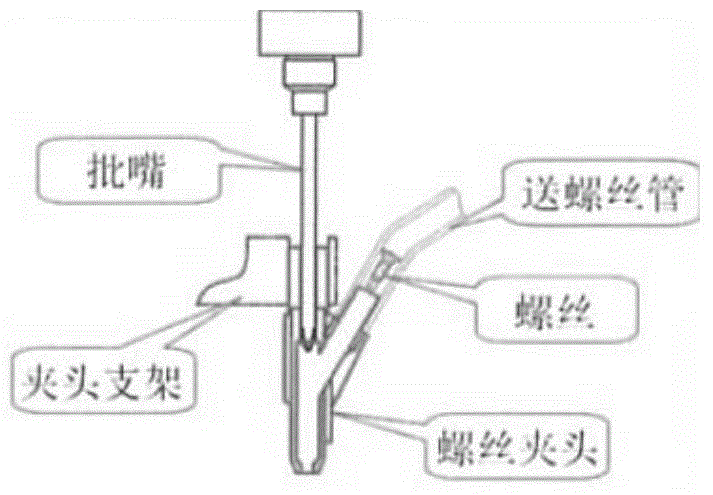
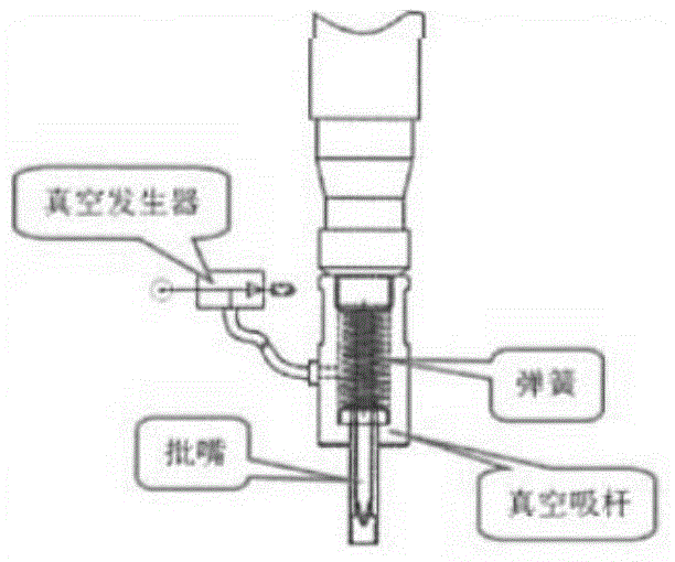
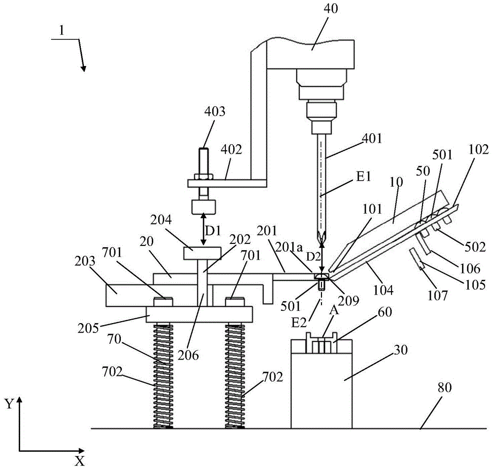
[0033] Figure 3 ~ Figure 8 It is a configuration diagram showing each state during operation of the automatic screw driving device according to the present embodiment. Figure 9 ~ Figure 10It is a schematic diagram which shows the rough structure of the screw conveying mechanism of the automatic screw driving apparatus which concerns on this embodiment. Figure 11 It is a schematic diagram which shows the rough structure of the holding part of the screw holding mechanism of the automatic screw driving apparatus concerning this embodiment. exist Figure 3 ~ Figure 8 In the shown rectangular coordinate system, the X-axis represents the horizontal direction, and the Y-axis represents the ...


PUM


Abstract

The invention relates to an automatic screw-in device for screws. The automatic screw-in device (1) for the screws comprises a screw conveying mechanism (10) used for conveying the screws (50) one by one, a screw keeping mechanism (20), a workpiece table (30) carrying a workpiece (60), and a screw screw-in mechanism (40). The screw keeping mechanism (20) contains the screws (50) output from an outlet (101) of the screw conveying mechanism (10) and keeps the postures of the screws (50). The screw screw-in mechanism (40) is used for screwing the screws (50) in the workpiece (60). The screws (50) are moved to the screw-in position (A) on the workpiece (60) from the outlet (101) of the screw conveying mechanism (10) in the state that the postures of the screws (50) are kept by the screw keeping mechanism (20) and the screws (50) are connected with the screw screw-in mechanism (40) in an abutting manner, and then the screws (50) are screwed into the workpiece (60) by the screw screw-in mechanism (40) in the state that the screws (50) are not kept by the screw keeping mechanism (20).

Description

technical field [0001] The invention relates to an automatic screw screwing device. Background technique [0002] Conventionally, the following two types of automatic screw-in devices have been adopted. That is, if figure 1 As shown, blow the screw along the screw pipe to the screw chuck by blowing through the pipeline, and then tighten the screw with the screwdriver. Additionally, if figure 2 As shown, the screw is sucked by vacuum suction, and then the screw is tightened by the bit. [0003] However, in the way of blowing through the pipeline, because the screw may be stuck or even turned over in the pipeline, the supply of screws with very short threads cannot be realized. In the vacuum adsorption mode, the vacuum suction rod structure is generally set on the elastic mechanism on the batch nozzle, which has limitations, so the screw screwing stroke cannot be too deep. In addition, in the vacuum suction method, the bottom of the screw is not supported, so the screw i...

Claims


Application Information

Patent Timeline
IPC IPC(8): B23P19/06
Inventor 张凯徐伟
Owner 吉田建材(苏州)有限公司
Why Eureka
Try Eureka