Bagging machine

A bagging machine and bagging technology, applied to the bagging machine for feed packaging and the field of grain, can solve the problems of physical injury, high labor intensity, and large occupied area, and achieve the convenience of production and manufacturing, improve work efficiency, and occupy an area small area effect

Inactive Publication Date: 2016-02-17
JIANGSU TAIPING ELECTROMECHANICAL EQUIP
View PDF6 Cites 3 Cited by
  • Summary
  • Abstract
  • Description
  • Claims
  • Application Information

AI Technical Summary

Problems solved by technology

The first reason is to reduce labor costs and improve work efficiency. Pure mechanical operation can work uninterruptedly for a long time, while the efficiency and durability of manual packaging are far from comparable to machinery; the second is to reduce the labor intensity of workers. The labor intensity of packaging is high and it is easy to cause harm to the body
[0003] However, some existing bagging machines also have disadvantages such as complex structure, high production cost, large floor space, and low stability, which restrict the promotion and application of automatic packaging equipment to a certain extent.

Method used


Image

  • Bagging machine
  • Bagging machine
  • Bagging machine

Examples


Embodiment Construction

[0038] In order to further illustrate the technical means adopted by the present invention and the technical effects achieved, the following will be described in detail in conjunction with the accompanying drawings.

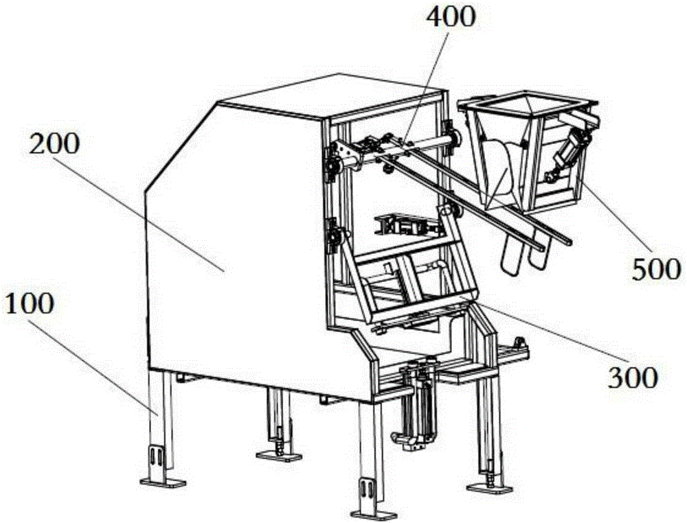
[0039] refer to figure 1 , which is a schematic diagram of the three-dimensional structure of the bagging machine of the present invention. In this embodiment, the bagging machine of the present invention includes a supporting chassis 100 , a casing 200 , a suction bag portion 300 , a bagging portion 400 and a bag clamping portion 500 . Wherein the casing 200 is disposed above the support chassis 100 .

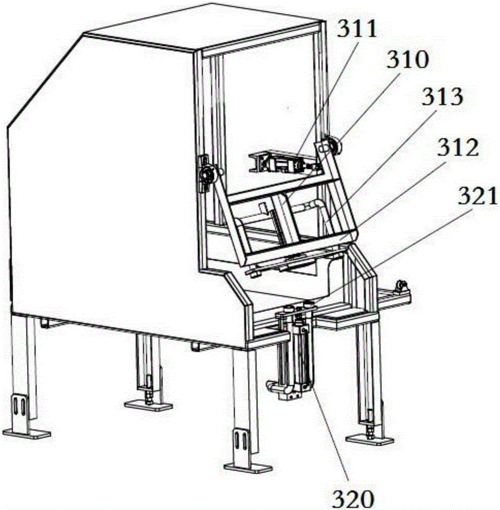
[0040] refer to figure 2 , which is a schematic structural diagram of the suction bag unit 300 in the bagging machine. In this embodiment, the suction bag unit 300 includes an upper suction bag device 310 and a lower suction bag device 320 . The upper suction bag device 310 includes a suction bag cylinder 311 , a movable support 312 and an upper suction duct...


PUM


Abstract

The invention provides a bagging machine. The bagging machine comprises a bottom rack, a housing arranged on the bottom rack, a bag suction part arranged in the housing, a bagging part and a bag clamping part arranged outside the housing, wherein the bag suction part is used for transferring bags, the bagging part is used for tensioning bag openings and sending the bags to the bag clamping part, and the bag clamping part is used for clamping the bags and then starting to fill the bags with grains or fodder. The bagging machine has the beneficial effects of being simple in structure, ingenious in design, low in manufacturing cost, small in occupied area, convenient to adjust, high in stability and the like.

Description

technical field [0001] The invention relates to a packaging machine, in particular to a bagging machine for grain and feed packaging. Background technique [0002] With the progress of society, automated machinery is gradually replacing labor, especially in the production process of food, feed and other industrial and agricultural bagged products, more and more enterprises use automated bagging technology to replace traditional manual bagging technology. The first reason is to reduce labor costs and improve work efficiency. Pure mechanical operation can work uninterruptedly for a long time, while the efficiency and durability of manual packaging are far from comparable to machinery; the second is to reduce the labor intensity of workers. The labor intensity of packaging is high, and it is easy to cause harm to the body. [0003] However, some existing bagging machines also have disadvantages such as complex structure, high manufacturing cost, large floor space, and low stab...

Claims


Application Information

Patent Timeline
Patent Type & Authority Applications(China)
IPC IPC(8): B65B43/30B65B43/46
CPCB65B43/30B65B43/465
Inventor 张明
Owner JIANGSU TAIPING ELECTROMECHANICAL EQUIP
Why Eureka
Try Eureka