Hydraulic tubing anchor

A technology of hydraulic tubing and center pipe, which is applied in the direction of wellbore/well components, earthwork drilling and production, etc. It can solve problems such as slip loosening and anchoring failure, and achieve the effect of preventing slip loosening

Inactive Publication Date: 2016-02-17
TIANJIN HUIZHU PETROLEUM EQUIP SCI & TECH CO LTD
View PDF1 Cites 2 Cited by
  • Summary
  • Abstract
  • Description
  • Claims
  • Application Information

AI Technical Summary

Problems solved by technology

For example, a Chinese patent discloses a tubing anchor, patent No. 200410039801.5. This tubing anchor can only be pushed by external pressure when the slips are fixed. If the external pressure decreases, the slips will loosen due to the lack of locking function. resulting in anchoring failure

Method used


Image

  • Hydraulic tubing anchor
  • Hydraulic tubing anchor

Examples


Embodiment Construction

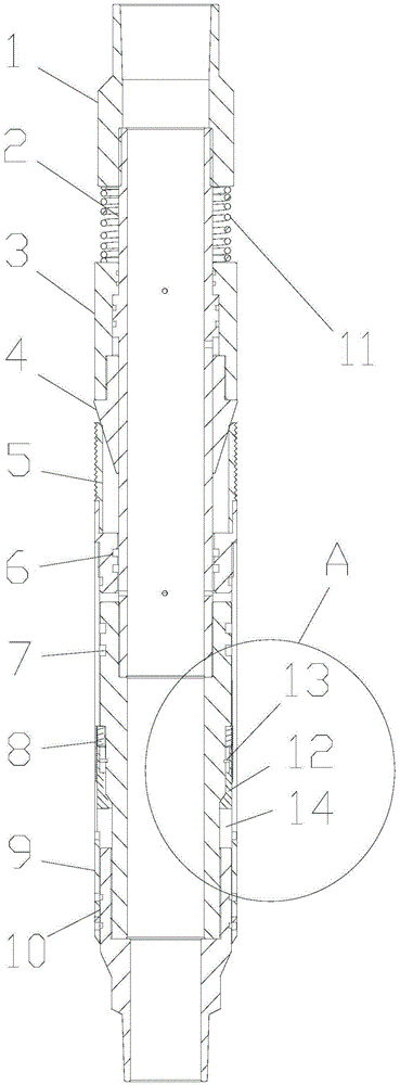
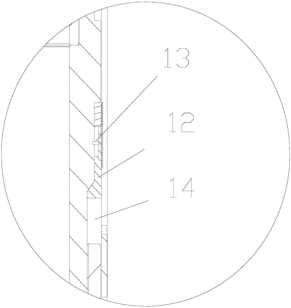
[0010] The specific implementation manner of the present invention will be described in detail below in conjunction with the accompanying drawings and preferred embodiments. Such as figure 1 and figure 2 As shown, a hydraulic oil pipe anchor includes an upper joint 1, a center pipe 2, an upper piston 3, a cone 4, a slip 5, a slip seat 6, a lower piston 7, a horse tooth ring 8, a horse tooth cylinder 9, a lower Joint 10, spring 11; the upper joint is fixed on the upper part of the central pipe, the spring is located between the upper piston and the upper joint and is sleeved on the central pipe, the central pipe and the central pipe A liquid hole is provided between the upper pistons, the cone is connected to the lower part of the upper piston, the lower part of the cone is matched with the slips, and the lower part of the slips is matched with the slip seat , the outer circumference of the slip seat is connected to the upper part of the horse tooth cylinder, the lower pisto...


PUM


Abstract

The invention relates to the technical field of oil field oil well drilling and production, in particular to a hydraulic tubing anchor. The hydraulic tubing anchor comprises an upper connector, a center pipe, an upper piston, a cone, a slip, a slip seat, lower pistons, a horse thread ring, a horse thread barrel, a lower connector and a spring. The upper connector is fixed to the upper portion of the center pipe, the spring is located between the upper piston and the upper connector and connected to the center pipe in a sleeving mode, the lower portion of the slip is matched with the slip seat, the periphery of the slip seat is connected with the upper portion of the horse thread barrel, and the horse thread ring is arranged between the lower piston and the horse thread barrel. A floating block is arranged between the lower pistons, inclined threads matched with the horse thread barrel are arranged on the horst thread ring and the floating block respectively, the floating block is connected with the lower pistons through shear pins, and the lower connector is connected with the lower portions of the lower pistons. The device has a one-way locking function, that is, in the upward moving process of the slip, the lower portion is fixed through the inclined threads, and the clamp is effectively prevented from loosening.

Description

technical field [0001] The invention relates to the technical field of oil well drilling and production in oil fields, in particular to a hydraulic oil pipe anchor. Background technique [0002] In oil extraction operations, in order to prevent oil pipes from wriggling and rotating up and down, resulting in eccentric wear of oil pipes and even loss of parts, the method of installing oil pipe anchors is usually used to anchor and protect oil pipes. The tubing anchor is usually installed under the production tubing string, and is a downhole device mainly used for anchoring the tubing string in production or measure wells. [0003] The anchoring function of the existing oil pipe anchor is mainly to use the relative movement between the upper joint and the slips when the center pipe is lowered, forcing the slips to open outwards, so that the slips on the outer side of the slips are firmly attached to the casing. The inner wall of the fixed center tube in the casing. When unanc...

Claims


Application Information

Patent Timeline
Patent Type & Authority Applications(China)
IPC IPC(8): E21B23/01
CPCE21B23/01
Inventor 阚红砖阚正玉
Owner TIANJIN HUIZHU PETROLEUM EQUIP SCI & TECH CO LTD
Why Eureka
Try Eureka