Mechanical floating ball water filling valve

A mechanical, floating ball technology, applied in the direction of mechanical equipment, lifting valves, valve details, etc., can solve problems such as incompatibility, design structure and raw material performance constraints, and achieve novel design, compact structure, pressure resistance and water level control Effect of Accuracy Improvement

Active Publication Date: 2016-02-17
CHUZHOU UNIV
View PDF5 Cites 0 Cited by
  • Summary
  • Abstract
  • Description
  • Claims
  • Application Information

AI Technical Summary

Problems solved by technology

The main defect is that this type of valve is restricted by the design structure and raw material performance, and is not suitable for working in a high-pressure environment

Method used


Image

  • Mechanical floating ball water filling valve

Examples


Embodiment Construction

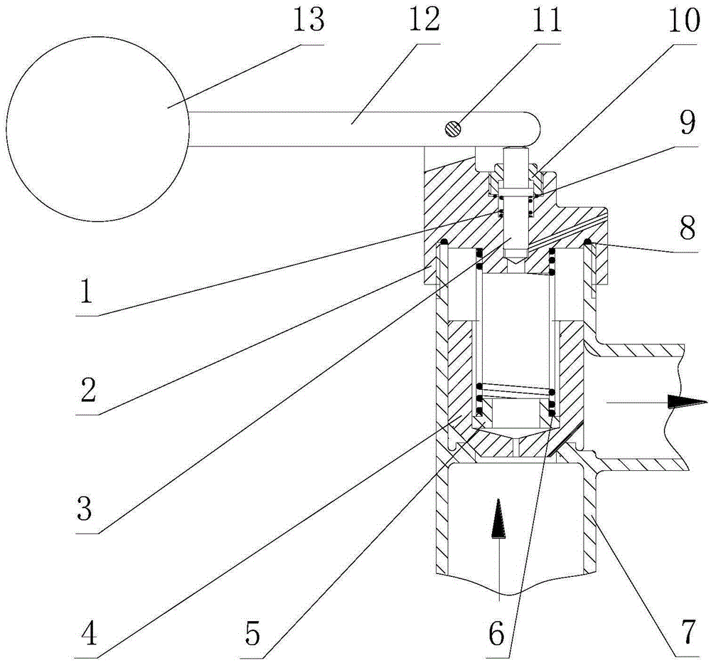
[0016] In this embodiment, refer to figure 1 , The mechanical floating ball filling valve includes a floating ball 13 and a lever 12. The floating ball 13 is installed at the front end of the lever 12, and the rear of the lever 12 is connected and fixed in an upper valve body 2 in a rotatable manner. The lower part of the valve body 2 is equipped with a lower valve body 7, and the lower valve body 7 is equipped with an inner valve 4; the inner valve 4 is provided with a spring seat 5, and the spring seat 5 has a positioning column. The positioning column is covered with a large spring 6, a large spring The upper and lower ends of the spring 6 are respectively connected to the lower end of the upper valve body 2 and the bottom of the spring seat 5; a needle valve 3 is installed in the upper valve body 2, the upper end of the needle valve 3 is in contact with the tail of the lever 12, and the lower end is connected to the upper valve body 2 The bottom of the inner valve 4 has a c...


PUM


Abstract

The invention discloses a mechanical floating ball water filling valve which comprises a floating ball and a lever. The floating ball is installed at the front end of the lever. The rear portion of the lever is fixedly connected into an upper valve body in a rotating mode. A lower valve body is assembled to the lower portion of the upper valve body. An inner valve is assembled into the lower valve body. A spring base is arranged in the inner valve and provided with a locating column. The locating column is sleeved with a large spring. The upper end and the lower end of the large spring are connected to the lower end of the upper valve body and the bottom of the spring base respectively. A needle valve is installed in the upper valve body. The upper end of the needle valve makes contact with the tail of the lever, and the lower end of the needle valve is in butt joint with a water passing hole of the upper valve body. A center damping hole is formed in the bottom of the inner valve. A water inlet hole is formed in the lower end of the lower valve body. A water outlet hole is formed in the side face of the lower valve body. The pressure affected face and the axial stroke of the needle valve are small, the diameter of the floating ball and the arm length of the lever are relatively small, the water level difference for opening and closing the valve through the floating ball is small, and control precision is high; compared with the prior art, the pressure withstanding value and the water level precision are controlled substantially, and the water filling valve is suitable for a high-pressure environment.

Description

Technical field [0001] The invention relates to the technical field of water supply control devices, in particular to a floating ball water supply valve. Background technique [0002] The existing mechanical floating ball filling valve is usually a structure in which a floating ball and a connecting rod are connected with a right-angle lever. The right-angle lever is pressed on the outer end of the ejector rod, and the pilot diaphragm sleeved by the ejector rod is in contact with the pressure relief target. . The force generated by the buoyancy ball lever of the float valve only balances the pressure of the pressure relief nozzle of the pilot valve, and the pressure relief nozzle is made of anti-fouling fluoroplastic material and is embedded in the center of the pilot valve body, directly with the control body. Connected. The pilot float valve constructed in this way uses a small float, a high shut-off capacity, and a compact overall structure, which can reduce costs and reduce...

Claims


Application Information

Patent Timeline
IPC IPC(8): F16K31/20F16K1/00
CPCF16K1/00F16K31/20
Inventor 谢正春王崴崴支新涛徐先洋邓景泉
Owner CHUZHOU UNIV
Why Eureka
Try Eureka