Hydraulic pipe clamping tool

A technology for clamping tooling and hydraulic pipes, which is applied in the direction of pipe supports, pipes/pipe joints/pipes, mechanical equipment, etc. It can solve the problems of high processing costs, unfavorable mass production, and long processing cycles, and achieve convenient and fast processing. The effect of installing or disassembling, improving the service life and reducing the degree of metal fatigue

Inactive Publication Date: 2016-02-17
四川海搏液压机械有限公司
View PDF10 Cites 1 Cited by
  • Summary
  • Abstract
  • Description
  • Claims
  • Application Information

AI Technical Summary

Problems solved by technology

[0002] At present, the pipe clamps used in construction machinery are generally non-standard parts. Each model needs to be equipped with different pipe clamps according to the type and size of its hydraulic pipes. This will result in a wide variety of pipe clamps, and different models need to be processed according to the model. Pipe clamp, which not only makes the processing cost high, but also has a long processing cycle, which is not conducive to mass production

Method used


Image

  • Hydraulic pipe clamping tool
  • Hydraulic pipe clamping tool
  • Hydraulic pipe clamping tool

Examples


Embodiment 1

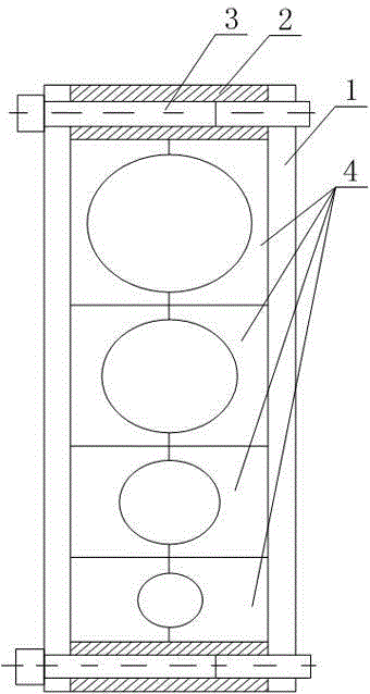
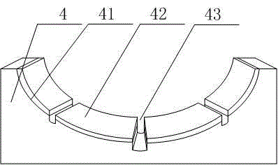
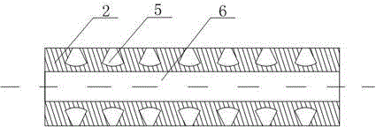
[0021] like figure 1 , figure 2 and image 3 As shown, the present embodiment includes two side plates 1 arranged in parallel, and the ends of the two side plates 1 are connected by bolts 3, and multiple A clamping block 4 is provided with a semicircular clamping surface 41 at the end of the clamping block 4, and a plurality of rectangular grooves 43 are formed on the clamping surface 41, and a plurality of rectangular grooves 43 The clamping surface 41 is divided into a plurality of independent circular arc segments, and elastic pads 42 are installed on the circular arc segments, and the two opposing clamping blocks 4 merge to form a closed circular clamp holding ring, and the diameters of a plurality of the circular holding rings are not the same, and also include two fastening plates 2, the middle part of the fastening plate 2 has a threaded hole 6 for the bolt 3 to pass through, in the A plurality of telescopic slots 5 are formed on the outer peripheral wall of the fas...


PUM


Abstract

The invention discloses a hydraulic pipe clamping tool which comprises two side plates, wherein a plurality of clamping blocks are respectively mounted on the side walls opposite to the two side plates; a clamping surface is arranged on the end part of each clamping block, and a plurality of rectangular grooves are formed in each clamping surface; each clamping surface is divided into a plurality of arc segments through the rectangular grooves, and elastic cushions are mounted on the arc segments; two opposite clamping blocks are merged into a closed circular clamping ring, and the diameters of a plurality of circular clamping rings are different. A plurality of telescopic grooves are formed in the peripheral wall of a securing plate, and the bottom surface of each telescopic groove is protruded on the direction vertically pointing to the center of the securing plate along the outer wall of the securing plate. A plurality of rectangular grooves of which the axes are parallel to the axis of the circle of each clamping surface are formed in the clamping surface. When each clamping block is extruded, the rectangular grooves have a certain width, so that the clamping part of the clamping block has a certain storage space when being deformed, therefore the metal fatigue degree in the clamping block is reduced, and the purpose of prolonging the service life of the clamping block is achieved.

Description

technical field [0001] The invention relates to a hydraulic pipe, in particular to a hydraulic pipe clamping tool. Background technique [0002] At present, the pipe clamps used in construction machinery are generally non-standard parts. Each model needs to be equipped with different pipe clamps according to the type and size of its hydraulic pipes. This will result in a wide variety of pipe clamps, and different models need to be processed according to the model. Pipe clamp, which not only makes the processing cost high, but also has a long processing cycle, which is not conducive to mass production. How to develop a pipe clamp that is applicable to different models and can be used for multiple hydraulic pipes of different sizes at the same time is a technical problem to be solved urgently by those skilled in the art. Contents of the invention [0003] The purpose of the present invention is to provide a hydraulic pipe clamping tool, which is convenient for simultaneousl...

Claims


Application Information

Patent Timeline
Patent Type & Authority Applications(China)
IPC IPC(8): F16L3/10
CPCF16L3/10
Inventor 谭继威邓国强
Owner 四川海搏液压机械有限公司
Why Eureka
Try Eureka