Artificial lateral line pressure detection method

A detection method and pressure technology, applied in the direction of fluid pressure measurement by changing ohmic resistance, can solve problems such as the failure of Doppler positioning technology, and achieve the effect of simplifying the sensing steps

Active Publication Date: 2016-02-17
OCEAN UNIV OF CHINA
View PDF5 Cites 24 Cited by
  • Summary
  • Abstract
  • Description
  • Claims
  • Application Information

AI Technical Summary

Problems solved by technology

Moreover, the flow field conditions containing frequency information are relatively special. When there is no vibration source, the Doppler positioning technology will fail

Method used


Image

  • Artificial lateral line pressure detection method
  • Artificial lateral line pressure detection method

Examples


Embodiment Construction

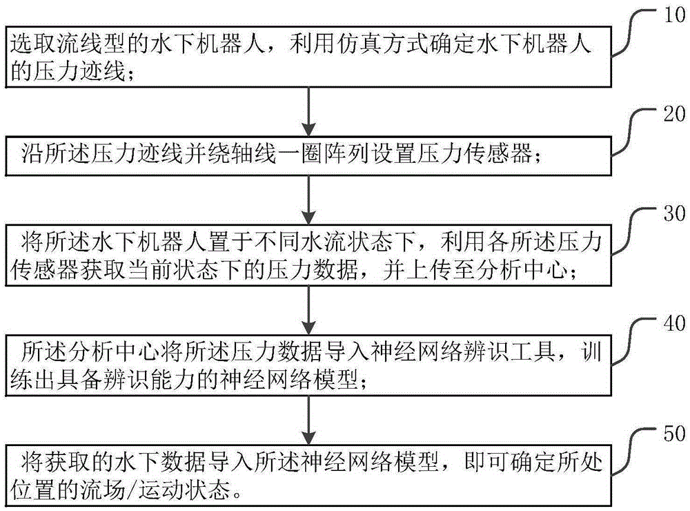
[0025] Such as figure 1 As shown, the artificial lateral line pressure detection method in one embodiment of the present invention generally includes the following steps:

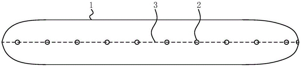
[0026] Step 10, select a streamlined underwater robot, and use simulation to determine the pressure trace of the underwater robot;

[0027] The streamlined underwater robot 1 has a regular geometric shape and good hydrodynamic performance, which facilitates the extraction of pressure data and the regular arrangement of measurement components.

[0028] Because when underwater robots 1 with different shapes cruise underwater, the distribution of pressure traces on the body surface is not the same. The simulation of this embodiment is to simulate and analyze the data obtained when the underwater robot 1 moves forward at a constant speed when the water flow has a certain flow rate and is in a static state. When determining the pressure trace of the underwater robot 1, the underwater robot 1 is also referred to...


PUM


Abstract

The invention provides an artificial lateral line pressure detection method which comprises the following steps: step 10, selecting a streamlined underwater robot, and determining the pressure trace of the underwater robot by a simulation mode; step 20, arraying pressure sensors along the pressure trace and around an axial line; step 30, putting the underwater robot in different water flow states, acquiring the pressure data of the current state by utilizing each pressure sensor, and uploading the pressure data to an analysis center; step 40, using the analysis center to import the pressure data into a neural network identification tool, and training to obtain a neural network model with an identification ability; and step 50, importing the acquired underwater data into the neural network model so that the flow field / motion state of the position can be determined. According to the invention, a set of artificial lateral line system is developed by utilizing the MEMS technology, and machine learning is carried out through the pressure data acquired by the sensors in the system, thereby realizing development of the ability of the underwater robot for environment identification.

Description

technical field [0001] The invention relates to the field of underwater environment exploration, in particular to a detection method for analyzing the water flow state at the current position of an underwater robot by using an artificial sideline method. Background technique [0002] Autonomous underwater vehicles (AUVs) usually use sonar systems and vision processing technology to explore the underwater environment or complete underwater related operations. However, some well-known defects limit the development of sonar and vision systems. For example, the long-term work of the sonar system will increase the power consumption of underwater robots, and the optical system cannot operate in dark and murky waters. Therefore, new underwater navigation mechanisms need to be developed urgently. [0003] The lateral line is an important hydrodynamic sensory organ found in fish and amphibians. It can help fish detect and process various hydrodynamic situations. The use of the later...

Claims


Application Information

Patent Timeline
Patent Type & Authority Applications(China)
IPC IPC(8): G01L9/06
Inventor 刘贵杰宫华耀王新宝王安逸刘鹏
Owner OCEAN UNIV OF CHINA
Why Eureka
Try Eureka