Automatic routing device used for transmission lines

A technology for wiring devices and transmission lines, which is applied in the direction of overhead lines/cable equipment, etc., can solve problems such as inflexible movements, exhaustion of physical strength of operators, and low work efficiency, so as to improve work efficiency, safety and reliability, and be practical Sex and economy, and the effect of improving the degree of automation

Active Publication Date: 2016-02-17
STATE GRID FUJIAN ELECTRIC POWER CO LTD +2
View PDF4 Cites 10 Cited by
  • Summary
  • Abstract
  • Description
  • Claims
  • Application Information

AI Technical Summary

Problems solved by technology

Such as the aging of insulators, fittings, anti-vibration hammers, etc., it is necessary to carry out maintenance work on transmission lines. There are more and more common problems such as replacing anti-vibration hammers, repairing wires, installing fittings, etc. However, the current operation methods are manually crawling upside down Arriving at the maintenance position to carry out transmission line maintenance operations, this operation method greatly exhausts the physical strength of the operators, and the maintenance posture is crawling, and the movements are not flexible. Not only is the work efficiency low, but the safety risks of the staff are high. Bigger security risk

Method used


Image

  • Automatic routing device used for transmission lines

Examples


Embodiment Construction

[0011] The present invention will be further described in detail below in conjunction with the accompanying drawings and specific embodiments.

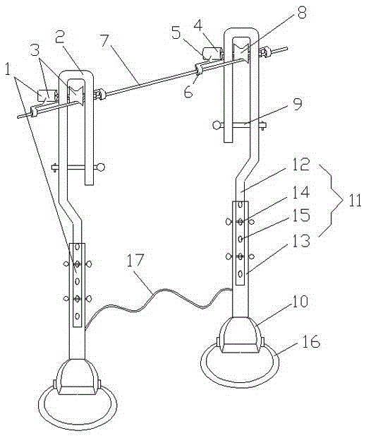
[0012] The automatic routing device for power transmission line of the present invention, such as figure 1 As shown, it includes two cable guides 1 with the same structure. The cable guide 1 includes an inverted U-shaped card slot 2. The upper part of the inverted U-shaped card slot 2 is provided with an electric drive mechanism 3. The electric drive mechanism 3 includes a drive motor. 4 and the motor fixing frame 5, the motor fixing frame 5 is slidably connected with the power line 7 through the guide sleeve 6 thereon, and the output shaft of the driving motor 4 runs through the two side plates of the inverted U-shaped card slot 2 and is connected with the inverted U-shaped card slot 2. The side plates are hinged, and the output shaft of the driving motor 4 is fixed with a driving wheel 8, which is closely matched with the power line...


PUM


Abstract

The invention relates to an automatic routing device used for transmission lines. The device comprises two routers with the same structure, wherein each router comprises an inverted U-shaped clamp groove; an electric driving mechanism is arranged in a groove of the inverted U-shaped clamp groove and comprises a drive motor and a motor fixing frame; the motor fixing frame is connected with a transmission line by a guide sleeve in a sliding manner; an output shaft of the drive motor penetrates through two side plates of the inverted U-shaped clamp groove and hinges the two side plates; a driving wheel is fixed on the output shaft, is in close fit with the transmission line so as to rotate on the transmission lines via the friction between the driving wheel and the transmission line and drives the router to walk on the transmission line; the driving motor is provided with control buttons so as to rotate forward, rotate backward or stop under the control of the control buttons; a safety catch for preventing the transmission line from coming off is arranged at a notch of the inverted U-shaped clamp groove; and the inverted U-shaped clamp groove is connected with a foot pedal downward, so that an operator can stand on the foot pedal to walk and carry out overhaul. The device has the effects of increasing the degree of automation of routing on the transmission lines and increasing the work efficiency and safety of overhaul.

Description

technical field [0001] The invention relates to the technical field of power grid maintenance, in particular to an automatic routing device for power transmission lines. Background technique [0002] In recent years, with the rapid development of the economy, the pace of power grid construction has been accelerating, and the corridors of overhead transmission lines have continued to increase. Passing through various harsh environments and harsh climates, overhead transmission lines have been operating in the open for a long time, and are often affected by the surrounding environment and nature. Various failures often occur due to the influence of changes. Such as the aging of insulators, fittings, anti-vibration hammers, etc., it is necessary to carry out maintenance work on transmission lines. There are more and more common problems such as replacing anti-vibration hammers, repairing wires, installing fittings, etc. However, the current operation methods are manually crawli...

Claims


Application Information

Patent Timeline
Patent Type & Authority Applications(China)
IPC IPC(8): H02G1/02
CPCH02G1/02
Inventor 陈昌庆林福王涛王矩峰刘小明阮肇华涂承谦彭晖亮陈海燕郑为凑周统明张自忠
Owner STATE GRID FUJIAN ELECTRIC POWER CO LTD
Why Eureka
Try Eureka