

A forming water roller device whose specifications can be adjusted arbitrarily within the production range
A production range and water roller technology, applied in the field of production equipment, can solve problems such as affecting production efficiency and production progress, wasting manpower and time, increasing the input cost of machine equipment, etc., to improve the scope of application, reduce cost input, The effect of improving production efficiency
- Summary
- Abstract
- Description
- Claims
- Application Information
AI Technical Summary
Problems solved by technology
Method used
Image

Examples
Embodiment 1
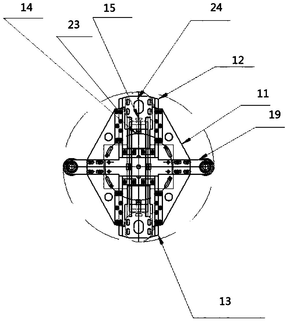
[0024] Such as figure 1 and image 3 Shown is a forming water roller device whose specifications can be adjusted arbitrarily within the production range, including: column b4, connecting rod wallboard 11, driving roller 2a16, driving roller a17, water roller fixing plate seat 18, water roller supporting plate 2a19 , water roller support plate 2b20 and drive roller b21, also includes first screw mandrel 9, connecting rod 10, water roller support plate 1a12, water roller support plate 1b13, nut b14, second screw mandrel 15 and nut c26.
[0025] The relationship between the above components is as follows:
[0026] The driving roller 2a16 is arranged between the column b4 and the connecting rod wallboard 11, the driving roller a17 and the driving roller b21 are all water-passing rollers, and the connecting rod wallboard 11 and the water roller fixing plate seat 18 are equipped with multi-position installation holes, the water roller support plate 2a19 is installed in the multi-p...
Embodiment 2
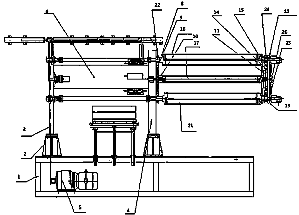
[0031] Such as Figure 1 to Figure 5A forming water roller device whose specifications can be adjusted arbitrarily within the production range is shown, including: large chassis 1, support seat 2, column a3, column b4, transmission motor 5, fixing cylinder 6, bead a7, nut a8, First screw rod 9, connecting rod 10, connecting rod wallboard 11, water roller support plate 1a12, water roller support plate 1b13, nut b14, second screw rod 15, nut c26, driving roller a17, water roller fixing plate seat 18 , Water roller support plate 2a19, water roller support plate 2b20, drive roller b21, first slider 22, bead b23, second slider 24 and third screw mandrel 25.
[0032] The relationship between the above components is as follows:
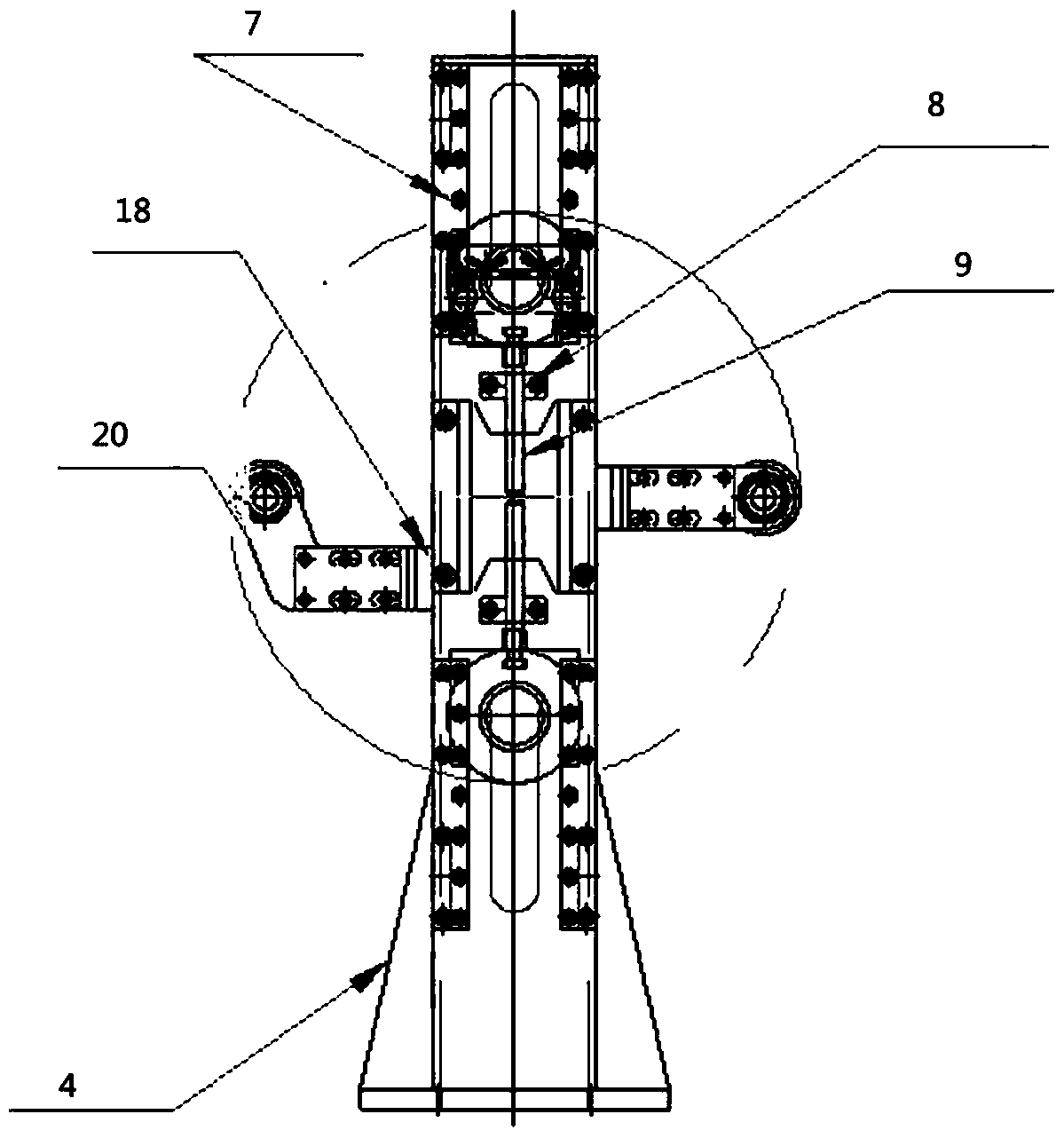
[0033] The support base 2 is fixed on the large chassis 1, the column a3 and the column b4 are respectively fixed on the two support bases 2, the transmission motor 5 is arranged under the large chassis 1, and the fixed cylinder 6 is set between the column...
Embodiment 3
[0038] Such as Figure 1 to Figure 5 A forming water roller device whose specifications can be adjusted arbitrarily within the production range is shown, including: large chassis 1, support seat 2, column a3, column b4, transmission motor 5, fixing cylinder 6, bead a7, nut a8, First screw rod 9, connecting rod 10, connecting rod wallboard 11, water roller support plate 1a12, water roller support plate 1b13, nut b14, second screw rod 15, nut c26, driving roller a17, water roller fixing plate seat 18 , water roller support plate 2a19, water roller support plate 2b20, driving roller b21 first slider 22, bead b23, second slider 24 and third screw mandrel 25, the connecting rod wallboard 11 and water roller fixing plate The seat 18 is provided with a multi-position installation hole, and the surrounding of the fixed cylinder 6 is provided with a telescopic frame, and the telescopic frame is composed of a heating base plate, a first connecting rod, a second connecting rod, a screw r...
PUM
 Abstract
Description
Claims
Application Information