Automatic tin welding line

A soldering and automatic technology, applied in welding equipment, printed circuits, manufacturing tools, etc., can solve the problems of increasing production costs, low production efficiency, and difficulty in meeting production needs, saving soldering time and improving production. Speed, the effect of reducing manual work

Active Publication Date: 2016-02-24
SUZHOU WISETECH AUTOMATION TECH CO LTD
View PDF6 Cites 17 Cited by
  • Summary
  • Abstract
  • Description
  • Claims
  • Application Information

AI Technical Summary

Problems solved by technology

[0002] In the electronics industry, it is often necessary to weld various electronic components to the circuit board. The welding of the circuit board requires high welding requirements and requires high technical requirements for the workers. Otherwise, it is easy to cause welding defects and lead to product scrapping. Manual welding The method of manual welding is also prone to burn people, and the production efficiency of manual welding is low, which is difficult to meet the production demand; and with the increasing labor cost, the manual welding method directly increases the production cost of the enterprise, and the soldering machine can be Realize automatic soldering, but a circuit board often needs to be soldered to multiple parts, which requires the use of multiple soldering machines for soldering operations at the same time

Method used


Image

  • Automatic tin welding line
  • Automatic tin welding line
  • Automatic tin welding line

Examples


Embodiment Construction

[0020] The present invention will be further described below in conjunction with the accompanying drawings and specific embodiments.

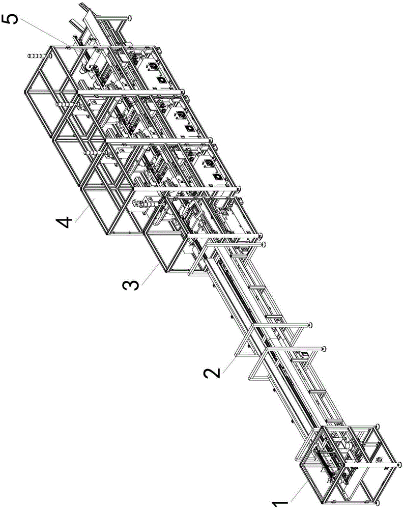
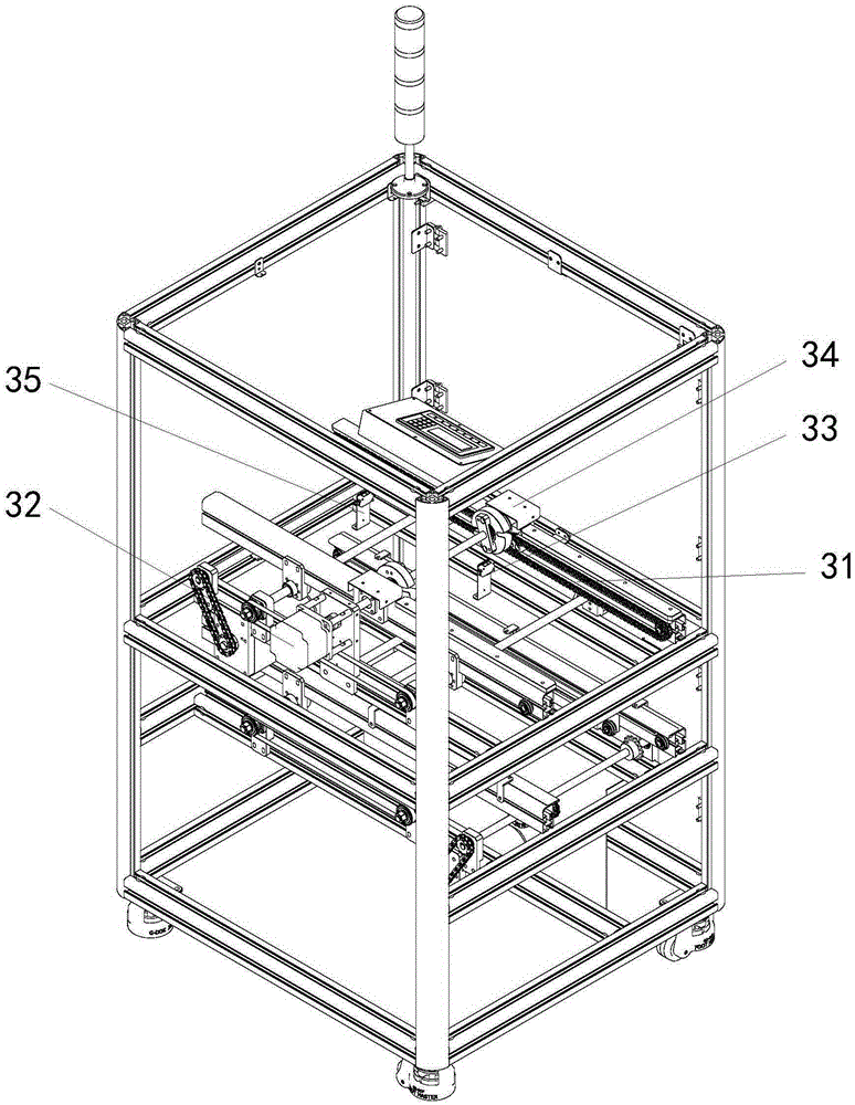
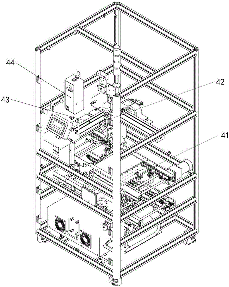
[0021] Such as Figure 1 to Figure 4 As shown, the automatic soldering line includes the elevator 1, the plug-in machine 2, the plate turning machine 3, the soldering machine 4 and the cleaning machine 5 connected in sequence. A conveying track is arranged between the elevator 1 and the plug-in machine 2. The elevator 1 is used for The carrier is lifted to the height of the conveying track, and the conveying track transports the carrier with the product to the plug-in machine 2 for plug-in, the turnover machine 3 flips the inserted product and then transports it to the soldering machine 4, and the soldering machine 4 pairs After the product is soldered, the product is transported to the cleaning machine 5 for cleaning, which also includes the return track for recovering the carrier arranged at the lower part of each mechanism. Placed on the ca...


PUM


Abstract

The invention discloses an automatic tin welding line. The automatic tin welding line comprises a lifter, a plugging machine, a board turning machine, a tin welding machine and a sweeper which are sequentially connected, wherein a conveying track is arranged between the lifter and the plugging machine and is used for conveying a carrier loaded with products to the plugging machine for plugging; the board turning machine is used for overturning the plugged products and then conveying the products to the tin welding machine; the tin welding machine is used for carrying out tin welding on the products and then conveying the products to the sweeper for sweeping. The automatic tin welding line further comprises a returning track arranged on the lower portions of the mechanisms and used for recycling the carrier. When the automatic tin welding line is used, the lifter lifts the carrier to the height of the conveying track, a worker puts the products to be machined on the carrier, the conveying track conveys the products to the plugging machine for plugging, the products are conveyed to the tin welding machine for tin welding after plugging is finished, the products are swept through the sweeper after tin welding is finished, the swept products are taken down by a worker at the output end of the sweeper, and the carrier is put on the returning track on the lower portion of the sweeper.

Description

technical field [0001] The invention relates to the field of automation equipment, in particular to an automatic soldering wire. Background technique [0002] In the electronics industry, it is often necessary to weld various electronic components to the circuit board. The welding of the circuit board requires high welding requirements and requires high technical requirements for the workers. Otherwise, it is easy to cause welding defects and lead to product scrapping. Manual welding The method of manual welding is also prone to burn people, and the production efficiency of manual welding is low, which is difficult to meet the production demand; and with the increasing labor cost, the manual welding method directly increases the production cost of the enterprise, and the soldering machine can be Automatic soldering is realized, but a circuit board often needs to be soldered to multiple parts, which requires the use of multiple soldering machines for soldering operations at t...

Claims


Application Information

Patent Timeline
Patent Type & Authority Applications(China)
IPC IPC(8): B23K1/00B23K3/00
CPCB23K1/0016B23K3/00B23K2101/42
Inventor 李胜波翟金双
Owner SUZHOU WISETECH AUTOMATION TECH CO LTD
Why Eureka
Try Eureka