Non-directional laser coding machine and coding method

A laser coding machine and laser coding technology, applied in the field of laser coding, can solve the problems of uncertain coding position and angle, and achieve the effect of precise laser coding, improving production efficiency and coding quality

Active Publication Date: 2018-12-04
广州市比美高智能系统科技有限公司
View PDF9 Cites 1 Cited by
  • Summary
  • Abstract
  • Description
  • Claims
  • Application Information

AI Technical Summary

Problems solved by technology

[0005] The present invention aims to solve the above problems of uncertain coding position and angle, and proposes a non-directional laser coding machine

Method used


Image

  • Non-directional laser coding machine and coding method

Examples


Embodiment 1

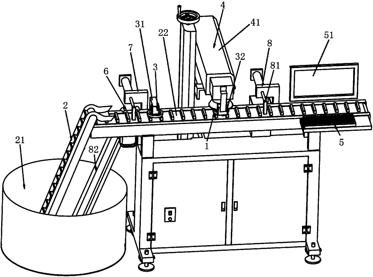
[0022] Such as figure 1 As shown, a non-directional laser coding machine includes a frame 1, a feeding system 2, a visual recognition system 3, a laser coding system 4, and a control system 5. The feeding system 2 includes a product container 21 and a product conveyor belt 22 for The product 6 is fed and the product 6 is conveyed on the frame 1, and the product sensor 7 is provided at the front end of the product conveyor belt 22; the visual recognition system 3 and the laser coding system 4 are set above the frame 1, and the visual recognition system 3 includes front and back visual The collector 31 and the non-directional visual collector 32 are used to capture product images, compare them with standard images, and calculate the offset of the position and angle of the current product. The laser marking system 4 has a laser marking machine 41 for Obtained product offset coordinates and angles, adjust the position of the product 6 and code the product 6, the control system 5 i...

Embodiment 2

[0025] A non-directional laser marking method, comprising the steps of:

[0026] (1) The product is transported by the feeding system into the coding area of ​​the rack;

[0027] (2) The control system receives the trigger signal from the product sensor and sends processing instructions to the visual recognition system;

[0028] (3) The visual recognition system performs processing, including capturing the product image, comparing it with the standard image, and calculating the position and angle offset of the current product, and the visual recognition system sends the processing result back to the control system;

[0029] (4) The control system processes the acquired data, including converting the offset based on the visual coordinate system and converting it into a coordinate value based on the laser marking system;

[0030] (5) The control system sends a coding request to the laser coding system;

[0031] (6) The laser coding system moves the object position in the codin...


PUM


Abstract

The invention discloses an astatic laser coding machine which comprises a rack, a feeding system, a visual identifying system, a laser coding system and a control system, wherein the feeding system is used for feeding a product and transmitting the product on the rack; the visual identifying system and the laser coding system are arranged above the rack; the visual identifying system is used for capturing a product picture, comparing the product picture with a standard picture, and counting a current product position and current product angular offset; the laser coding system is used for regulating the product position and coding the product according to the obtained product offset coordinates and the obtained product offset angle; the control system is connected with the visual identifying system, the laser coding system and a product sensor, and is used for sending a trigger signal sent by the product sensor and then sending a processing instruction to the visual identifying system, and processing the data obtained by the visual identifying system; and the laser coding system is used for sending the coding instruction. The astatic laser coding machine can be used for realizing laser coding with a precise position, so that the production efficiency and the coding quality are greatly improved.

Description

technical field [0001] The invention relates to the technical field of laser coding, in particular to a non-directional laser coding machine. Background technique [0002] Laser coding refers to printing text or patterns and other information on the surface of the product in the form of laser marking, such as the production date, batch number, serial number, model, etc. of the product. It is currently widely used in various industries. [0003] In the application of laser coding, the printing position and angle are generally set by adjusting the physical position of the laser coding machine and adjusting the relative position of the coding object in the template file of the coding software. After setting, the position and angle of the code are fixed each time the code is printed, but in actual production, the position and direction of each product when entering the code area are different, so the actual printing effect is: The position and angle of the printed information o...

Claims


Application Information

Patent Timeline
Patent Type & Authority Patents(China)
IPC IPC(8): B23K26/362B23K26/03B23K26/70
CPCB23K26/032
Inventor 邓文韬
Owner 广州市比美高智能系统科技有限公司
Why Eureka
Try Eureka