Automatic yarn laying mechanism of glass fiber pultrusion grid continuous production line

A glass fiber and production line technology, applied in the field of automatic yarn laying mechanism of glass fiber pultrusion grid continuous production line, can solve the problems of high manufacturing cost, large space required, many parts and so on, and achieves good yarn laying density, Good yarn laying effect and compact structure

Active Publication Date: 2016-02-24
JIANGSU JIUDING NEW MATERIAL CO LTD
View PDF5 Cites 3 Cited by
  • Summary
  • Abstract
  • Description
  • Claims
  • Application Information

AI Technical Summary

Problems solved by technology

[0008] This device can realize the continuous production of FRP grating, which improves the production efficiency, but it also has certain defects: the longitudinal fiber laying mechanism of its yarn laying mechanism is composed of a creel, which is arranged on the creel and the mold The yarn shaft corresponding to the longitudinal groove of the plate is formed, and the transverse fiber laying mechanism is composed of the second creel, the horizontal yarn shaft fixed on the creel, and the yarn laying mechanism; the mechanism is an open yarn laying structure, The glass fiber yarn cannot be completely laid in the longitudinal and transverse grooves of the mold, even if it is pressed by pressing rollers and other components; and there are many parts and assembly processes, and it is difficult to control its installation accuracy, which requires repeated debugging, which is time-consuming and laborious ; while laying yarn, it is necessary to use an independent press-in mechanism to compress the glass fiber yarn in the mold, which requires a large space, so the grid production line using the yarn laying mechanism has a large footprint and high manufacturing costs. shortcoming
In addition, during the yarn laying process, horizontal yarn laying can be realized by controlling the reciprocating movement of the weft yarn shaft or the fiber yarn on the weft yarn shaft, but no further disclosure has been made

Method used


Image

  • Automatic yarn laying mechanism of glass fiber pultrusion grid continuous production line
  • Automatic yarn laying mechanism of glass fiber pultrusion grid continuous production line
  • Automatic yarn laying mechanism of glass fiber pultrusion grid continuous production line

Examples


Embodiment Construction

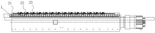
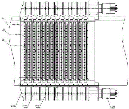
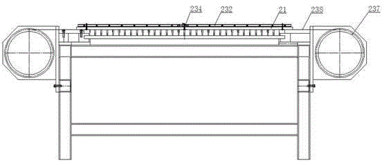
[0028] Such as figure 1 , 2 , 3, mainly includes the longitudinal yarn laying mechanism 22 and the horizontal yarn laying mechanism 23 installed on the fixed mold 21 of the reinforcing fiber insertion section; the specific structure is as follows:

[0029] Reinforced fibers are inserted into the segment stent 21, such as Figure 4 As shown, the fixed mold 21 of the reinforced fiber inserting section is arranged on the moving channel of the moving mandrel of the production line frame, on which are distributed a number of horizontal yarn laying areas 21a and longitudinal yarns distributed along the moving direction of the moving mandrel and arranged at intervals. Laying area 21b, wherein, each weft yarn laying area 21a has a weft yarn laying groove 211 extending perpendicular to the moving direction of the moving mandrel; the longitudinal yarn laying area 21b has a longitudinal yarn Yarn laying slot 212 or several longitudinal yarn laying slots 212 distributed along the moving...


PUM


Abstract

The invention relates to an automatic yarn laying mechanism of a glass fiber pultrusion grid continuous production line. The automatic yarn laying mechanism is characterized by comprising a reinforcement fiber placement section fixing template, a longitudinal yarn laying mechanism and a horizontal yarn laying mechanism; a plurality of horizontal yarn laying regions and a plurality of longitudinal yarn laying regions distributed in the movement direction of a movement core template and arranged at intervals are distributed on the reinforcement fiber placement section fixing template; the longitudinal yarn laying mechanism comprises a longitudinal yarn installation base, a pressing sheet and a plurality of pressing sheets distributed in the direction perpendicular to the movement direction of the movement core template; and the horizontal yarn laying mechanism comprises a horizontal yarn installation base, and a horizontal-yarn linear guide rail extending in the direction perpendicular to the movement direction of the movement core template and a horizontal yarn sliding assembly are installed on the horizontal yarn installation base. By means of the automatic yarn laying mechanism, automatic and continuous yarn laying can be achieved, and core conditions are provided for smoothly manufacturing a pultrusion glass fiber grid; and after overall sub-assembling and adjustment are carried out, the automatic yarn laying mechanism is installed on the reinforcement fiber placement section fixing template, modular assembling is achieved, installing accuracy is guaranteed, and independent part replacement can be carried out during maintaining.

Description

technical field [0001] The invention relates to a glass fiber grid production equipment, in particular to an automatic laying mechanism for a continuous production line of glass fiber pultrusion grids. Background technique [0002] Fiberglass grating is a kind of multi-hole plate-shaped material processed with glass fiber as the reinforcing material and resin as the main matrix. It can be widely used in construction, petroleum, chemical industry, electronics, marine exploration and other industries, and has a large application market. [0003] At present, there are three known structures of fiber-reinforced plastic grids, namely molded grids, molded grids and pultruded profile assembled grids. [0004] The molded grid is formed by arranging continuous reinforcing fibers in an open mold and pouring a thermosetting resin and curing under appropriate conditions. Although the reinforcing fibers of the molded grid are continuous fibers, because it is formed by an open single-pie...

Claims


Application Information

Patent Timeline
Patent Type & Authority Applications(China)
IPC IPC(8): B29C70/34B29C70/52
CPCB29C70/34B29C70/52
Inventor 储开明沈达泉崔伯军姜鹄
Owner JIANGSU JIUDING NEW MATERIAL CO LTD
Why Eureka
Try Eureka