
Non-linear particle impact damper

A particle collision and damper technology, which is applied to bridge parts, building components, bridges, etc., can solve the problem of narrow frequency band of vibration reduction, and achieve the effects of improving energy consumption efficiency, saving space, and simple structure

Inactive Publication Date: 2016-02-24
TONGJI UNIV
View PDF8 Cites 26 Cited by
  • Summary
  • Abstract
  • Description
  • Claims
  • Application Information

AI Technical Summary

Problems solved by technology

[0004] In order to solve the problem that the traditional tuned mass damper has a narrow damping frequency band and can only provide a specific tuning frequency in the horizontal direction, and reduce the cost of the damper, the purpose of the present invention is to propose a nonlinear particle collision damper, which The device is improved on the basis of the traditional tuned mass damper, and 8 variable stiffness springs are arranged circumferentially and symmetrically around the additional mass, and at the same time, particle groups are arranged in the damper cavity

Method used


Image

  • Non-linear particle impact damper
  • Non-linear particle impact damper

Examples


Embodiment 1

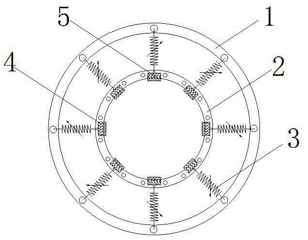
[0018] Embodiment 1: as figure 1 As shown, it is an embodiment of a nonlinear particle impact damper of the present invention, which mainly includes an additional flange outer ring 1, a mass inner ring 2, a variable stiffness spring 3, a damper cavity unit 4 and a particle group 5.

[0019] The additional flange outer ring 1 is connected to the main body system through bolts, the mass inner ring 2 is connected to the flange outer ring 1 through 8 variable stiffness springs 3 uniformly and symmetrically arranged in the circumferential direction, and the damper cavity unit 4 is a single cuboid or cylinder Body structure, a layer of particle group 5 is arranged inside each damper cavity unit 4, the particle group 5 is composed of round or irregular particles, and the material can be any one or more of metal, concrete, glass or ceramics kind. By properly setting the stiffness of the spring method and the size of the additional mass, different stiffnesses can be provided in all di...


PUM


Abstract

The invention relates to a non-linear particle impact damper. The non-linear particle impact damper comprises an additional flange outer ring, a mass inner ring, variable stiffness springs, damper cavity units and particle groups. The additional flange outer ring is connected with a main system through bolts, the additional flange outer ring and the mass inner ring are arranged concentrically, in the horizontal direction, the mass inner ring is connected with the additional flange outer ring through the variable stiffness springs, a spring unit is composed of eight variable stiffness springs which are arranged uniformly and symmetrically in the circumferential direction, each damper cavity unit is a single cuboid or cylinder structure, the interior of each cavity is provided with a layer of the particle groups, and the particle groups are composed of round or out-of-shape metal or nonmetal particles. By reasonably arranging the rigidity of the variable stiffness springs and the added mass, different rigidities can be provided in all directions on the horizontal plane in order to tune the frequency of the structure. Under the action of wind / earthquake, the non-linear particle impact damper provides different rigidities in all directions to tune the frequency, spring rigidities are not changed linearly, and kinetic energy of the structure can be transferred and dissipated through friction and impact of the particle groups.

Description

technical field [0001] The invention relates to a nonlinear particle collision damper, which is connected to the basic structure through variable stiffness springs arranged symmetrically in the circumferential direction, and particles are filled inside one or more damper cavity units, and energy is dissipated through multiple collisions of large and small particles , which belongs to the field of vibration control of civil structures (including high-rise buildings, high-rise structures and bridge structures, etc.). Background technique [0002] In recent years, passive control technologies such as base isolation, energy dissipation, and tuned vibration control have been widely used in civil engineering at home and abroad because of their simple concept, clear mechanism, low cost, and remarkable shock absorption effect. Among them, the tuned mass damper (TMD) has been widely welcomed for its simple construction, convenient operation, and remarkable vibration reduction effect....

Claims


Application Information

Patent Timeline
IPC IPC(8): E04B1/98E01D19/00E01D19/04
CPCE01D19/00E01D19/041E04H9/0215
Inventor 鲁正杨玉玲张泽楠
Owner TONGJI UNIV
Learn More