
Sealing device for high-temperature and high-pressure rotating machinery

A high temperature and high pressure, sealing device technology, applied in the direction of engine sealing, mechanical equipment, engine components, etc., can solve the problems of short service life, high maintenance frequency, nitrogen can not fully take away heat, etc., to achieve long service life, safety High, improve the effect of operating conditions

Active Publication Date: 2016-02-24
SICHUAN SUNNY SEAL
View PDF6 Cites 4 Cited by
  • Summary
  • Abstract
  • Description
  • Claims
  • Application Information

AI Technical Summary

Problems solved by technology

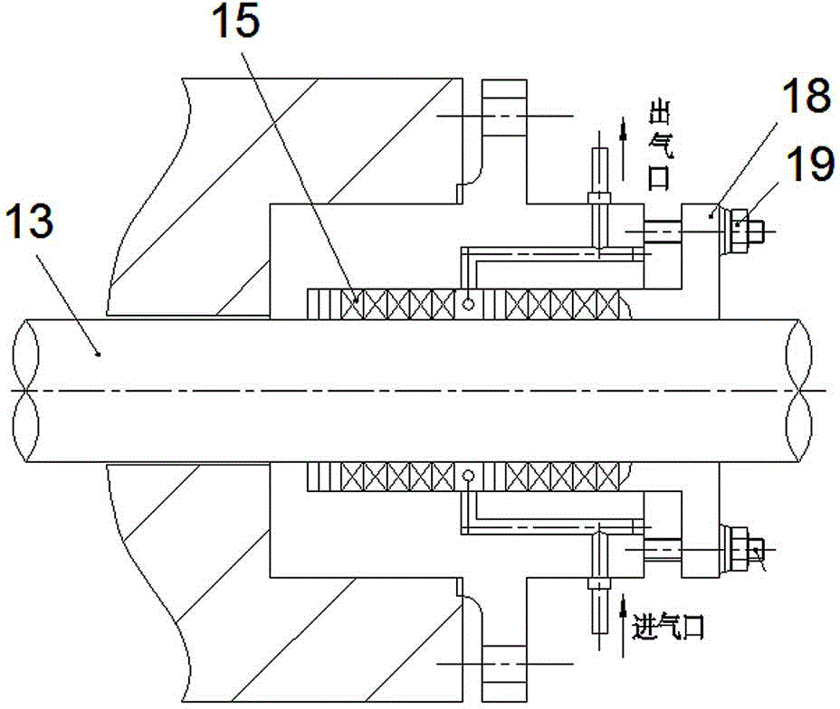
Due to the tight embrace of the packing (15) and the shaft (13), the rotation of the shaft needs to overcome the friction and the loss of shaft power
At the same time, the friction heat is large, and the nitrogen cannot fully take away the heat
Due to high temperature friction, the shaft is easily worn out, and the seal will not work after the gap is worn out. The screw (19) on the gland (18) must be tightened many times during the operation of the equipment, making maintenance difficult
Therefore, the sealing structure is essentially a packing seal. Due to its short service life, large power loss and high maintenance frequency, it is only suitable for high-temperature and high-pressure equipment with low speed and short service life.

Method used


Image

  • Sealing device for high-temperature and high-pressure rotating machinery
  • Sealing device for high-temperature and high-pressure rotating machinery
  • Sealing device for high-temperature and high-pressure rotating machinery

Examples


Embodiment Construction

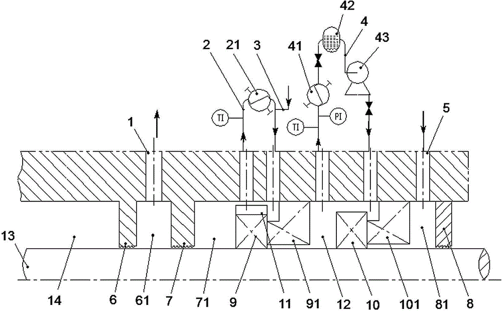
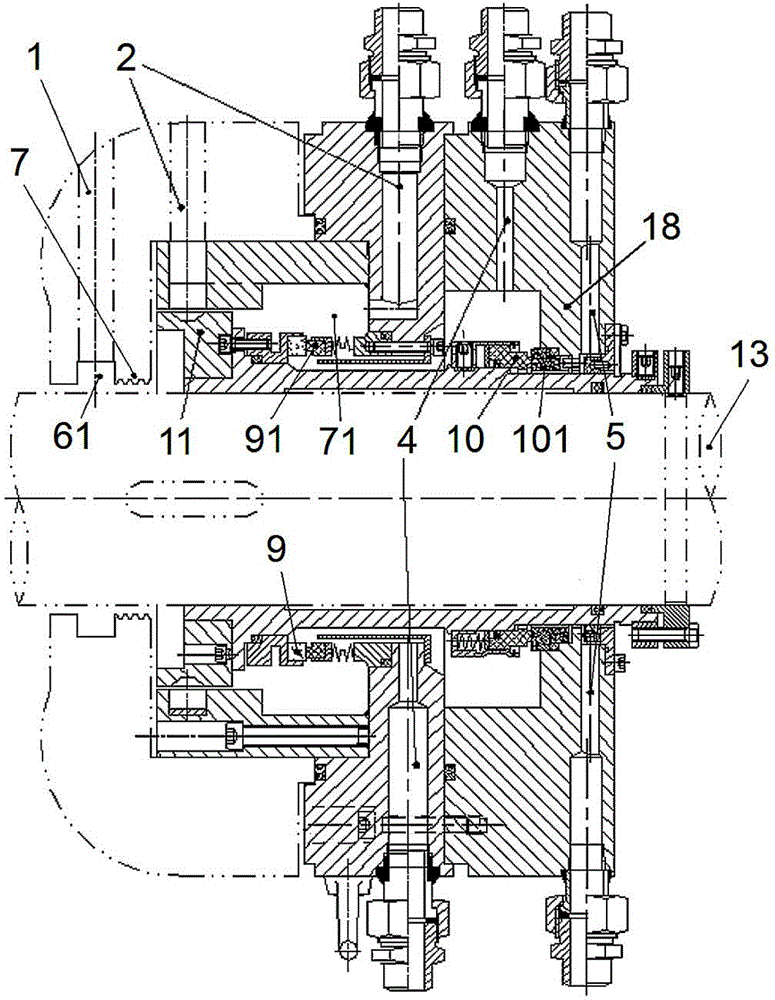
[0024] Such as figure 2 As shown, the sealing device for high-temperature and high-pressure rotary machines of the present invention includes two groups of rotating seal rings and rotary seal rings that are arranged adjacent to each other at the end of the rotating shaft 13 across the high-temperature and high-pressure medium zone 14 in sequence. An end face sealing unit composed of a stationary sealing ring fixedly connected to the base. in:

[0025] ——On the side of the high temperature and high pressure medium area of ​​the first end face sealing unit (ie the main sealing unit) sealed by the metal bellows composed of the first rotating seal ring 9 and the first stationary seal ring 91, there is an adjacent rotary The shaft 13 is spaced apart from a pair of throttling units 6 and 7 to form a depressurization zone 61 . The decompression area 61 can communicate with the high-temperature and high-pressure medium area 14 and the sealing chamber 71 of the first end face sealin...


PUM


Abstract

Provided is a sealing device for high-temperature and high-pressure rotating machinery. End face sealing units are arranged at the end of a rotating shaft penetrating through a high-temperature and high-pressure medium area and are composed of rotary sealing rings and stationary sealing rings, wherein the rotary sealing rings can rotate along with the rotating shaft, and the stationary sealing rings are connected with a base in a positioned mode. A depressurization area is adjacently arranged on the high-temperature and high-pressure medium area direction side of the first end face sealing unit composed of the first rotary sealing ring and the first stationary sealing ring, and the depressurization area is composed of throttling units, communicated with the high-temperature and high-pressure medium area and a sealed cavity of the first end face sealing unit simultaneously, and provided with a pressure reducing area communicated with an external low-pressure unit. The sealed cavity of the first end face sealing unit is provided with a cooling circulation channel with a heat exchange structure. According to the sealing device, conveyed high-temperature and high-pressure media are cooled and depressurized, and therefore the sealing device is capable of adapting to reliable sealing of the high-temperature and high-pressure media, long in service life, high in safety, capable of achieving zero leakage of the high-temperature and high-pressure media and capable of being widely used for sealing the rotating machinery of high-end equipment in the field of petroleum, the chemical industry, nuclear power and the military industry under high-temperature and high-pressure working conditions.

Description

technical field [0001] The invention relates to a mechanical sealing device for rotary dynamic sealing, which is suitable for rotary dynamic sealing under high temperature and high pressure combined working conditions. Background technique [0002] At present, the rotary shaft seal that solves the high-temperature medium working condition usually uses a metal bellows seal, which can withstand a temperature of 450°C, but at the same time, the pressure it can withstand is limited, and the maximum pressure does not exceed 6MPa. For the rotary shaft seal under high-pressure medium conditions, spring-type mechanical seals can be used. At present, the maximum withstand pressure can reach 15MPa, but the spring-type seal structure is limited by the rubber parts, and its withstand temperature generally does not exceed 300°C. [0003] When the temperature exceeds 300°C and the pressure exceeds 6MPa, the sealing of the rotating shaft is currently a difficult problem to solve. Due to t...

Claims


Application Information

Patent Timeline
IPC IPC(8): F16J15/16F16J15/54
Inventor 张有华王威伍娜朱晓波任俊明周昌奎侯晓东
Owner SICHUAN SUNNY SEAL
Learn More