Circulating water cooling device

A heat dissipation device and circulating water technology, applied in lighting devices, cooling/heating devices of lighting devices, lighting and heating equipment, etc., can solve the problems of low heat dissipation efficiency, affecting the light efficiency and life of LED light sources, high temperature of LED light sources and power supplies, etc. problem, to achieve the effect of simple gate valve structure

Active Publication Date: 2018-10-16
WUXI FANGSHENG HEAT EXCHANGER MFG
View PDF9 Cites 0 Cited by
  • Summary
  • Abstract
  • Description
  • Claims
  • Application Information

AI Technical Summary

Problems solved by technology

[0003] The application of LED has been plagued by heat dissipation problems, which seriously affect the light efficiency and lifespan of LED light sources. The heat dissipation of LED lights generally depends on radiators. Traditional radiators are generally closed cylinders, and some Although the fins have achieved the basic purpose of heat dissipation, the closure of the radiator makes the air inside the radiator unable to circulate with the outside air in time, resulting in low heat dissipation efficiency, resulting in high temperature of the LED light source and power supply, which affects the light efficiency of the LED. and life, and in order to make the effect of the radiator better, the existing radiator will also open cooling holes on the outer wall. The design is too small, although it plays the role of dust-proof and moisture-proof for the LED lamp, the heat generated by the LED lamp still cannot be dissipated smoothly, and the heat dissipation hole is too small, it will be easily blocked by dust over time, resulting in heat dissipation The hole cannot achieve the purpose of heat dissipation, which will inevitably affect the service life of the LED lamp

Method used


Image

  • Circulating water cooling device

Examples


Embodiment Construction

[0015] The present invention will be described in further detail below by means of specific embodiments:

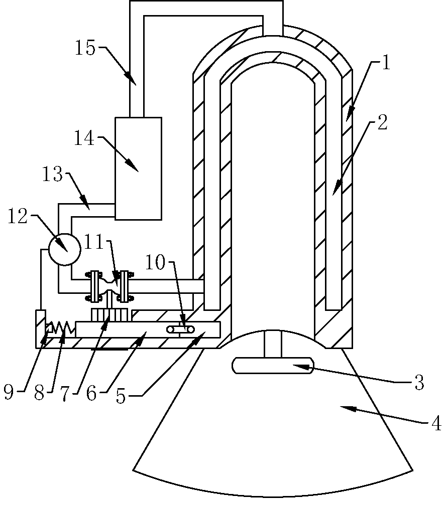
[0016] The reference signs in the drawings of the specification include: heat dissipation cover 1, cavity 2, LED lamp 3, LED lampshade 4, rubber block 5, rack 6, gear 7, spring 8, switch 9, connector 10, gate valve 11, Water pump 12, water inlet pipe 13, cooling box 14, water outlet pipe 15.

[0017] Example basic reference figure 1 Shown: a circulating water type cooling device, including a cooling cover 1, an LED lampshade 4 is fixedly connected under the cooling cover 1, an LED lamp 3 is arranged inside the LED lampshade 4, a cavity 2 is arranged inside the cooling cover 1, and the bottom of the cavity 2 is connected to There is a water inlet pipe 13, an outlet pipe 15 is connected to the upper part of the cavity 2, a cooling box 14 is connected between the water inlet pipe 13 and the water outlet pipe 15, a gate valve 11 is arranged on the water inlet pipe 13, and a ...


PUM


Abstract

The invention relates to a heat dissipation device and discloses a water circulation type heat dissipation device. The water circulation type heat dissipation device comprises a heat dissipation cover. A cavity is formed in the heat dissipation cover, the bottom of the cavity is connected with a water inlet pipe, a water outlet pipe is connected to the upper part of the cavity, and a cooling box is connected between the water inlet pipe and the water outlet pipe. The water inlet pipe is provided with a valve, and a water pump is arranged between the valve and the cooling box. The heat dissipation cover is provided with a groove, a rack is connected into the groove in a sliding mode, and an expansion body is arranged between the rack and the bottom wall of the groove in an abutting mode. The rack is meshed with a gear, and the gear is fixedly connected to a valve rod of the valve. The rack is connected with an elastic part, the side, away from the rack, of the elastic part is fixed, and a switch for controlling the water pump is arranged at the part, located on one side of the elastic part, of the rack. Compared with the prior art, the size of the expansion body changes with the temperature change and drives the rack to move for turning on or turning off the water pump and opening or closing the valve, and therefore the heat dissipation performance is improved, and the dust prevention and moisture prevention effect is realized.

Description

technical field [0001] The invention relates to a cooling device, in particular to a circulating water type cooling device. Background technique [0002] LED is a semiconductor that can convert electrical energy into visible light. Its energy consumption is only 1 / 10 of incandescent lamps, and 1 / 4o of ordinary energy-saving lamps. In addition to the advantages of environmental protection and energy saving, LED lamps also have long life and high luminous efficiency. , No radiation and many other advantages. Therefore, as an upgraded product of the next generation of lighting, LED is an emerging industry with great development potential. [0003] The application of LED has been plagued by heat dissipation problems, which seriously affect the light efficiency and life of LED light sources. The heat dissipation of LED lights generally depends on radiators. Traditional radiators are generally closed cylinders, and some Although the fins have achieved the basic purpose of heat d...

Claims


Application Information

Patent Timeline
Patent Type & Authority Patents(China)
IPC IPC(8): F21V29/57
Inventor 鲁永忠
Owner WUXI FANGSHENG HEAT EXCHANGER MFG
Why Eureka
Try Eureka