an upward air burner

A burner and air intake channel technology, which is applied in the field of upward air intake burners, can solve the problems of incomplete combustion of gas and insufficient air supplementation, and achieve the effect of stable gas flow and improved combustion rate

Active Publication Date: 2018-07-20
CHINABEST HOME APPLIANCE
View PDF9 Cites 0 Cited by
  • Summary
  • Abstract
  • Description
  • Claims
  • Application Information

AI Technical Summary

Problems solved by technology

The upward air intake burner is also widely used, but the upward air intake burner also has its disadvantages. The main reason is that the air supply is insufficient, which may easily lead to incomplete combustion of the gas. In order to supplement enough air, some burners have an air channel that is easy to allow soup, etc. to flow into it. into the burner

Method used


Image

  • an upward air burner
  • an upward air burner
  • an upward air burner

Examples


Embodiment Construction

[0034] Below in conjunction with accompanying drawing and specific embodiment the present invention is described in further detail:

[0035] Such as Figure 1 to Figure 10 Shown, a kind of upper intake air burner is characterized in that: comprising

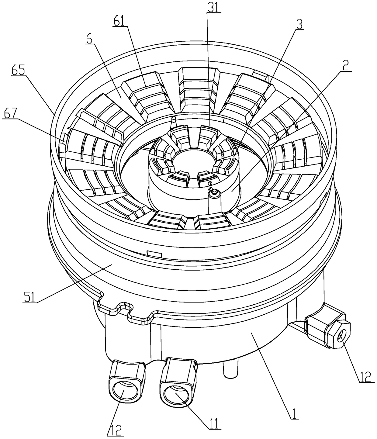
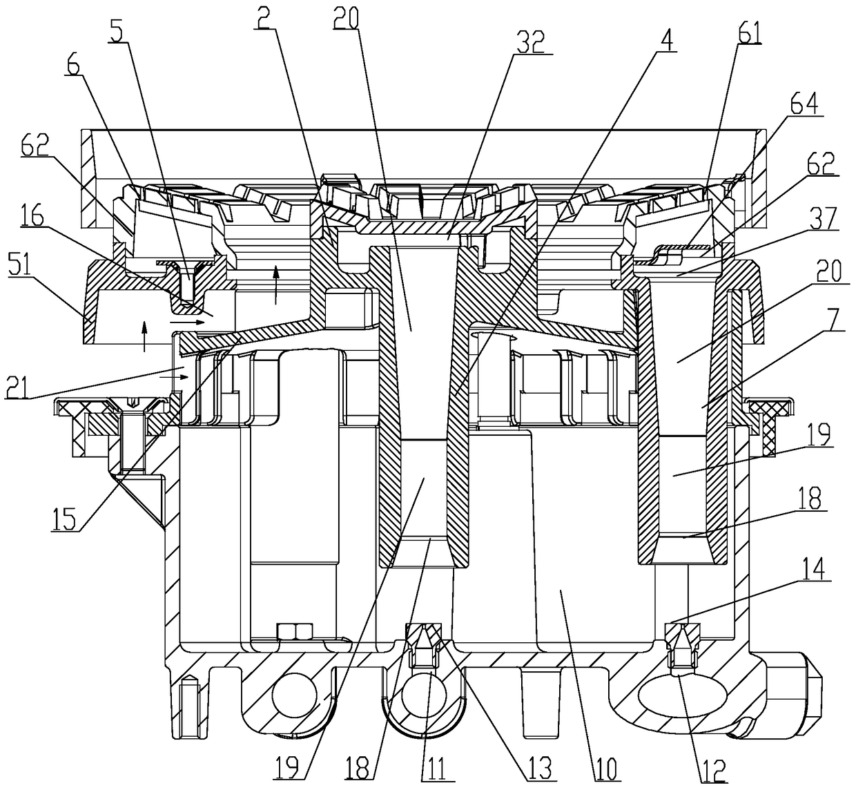
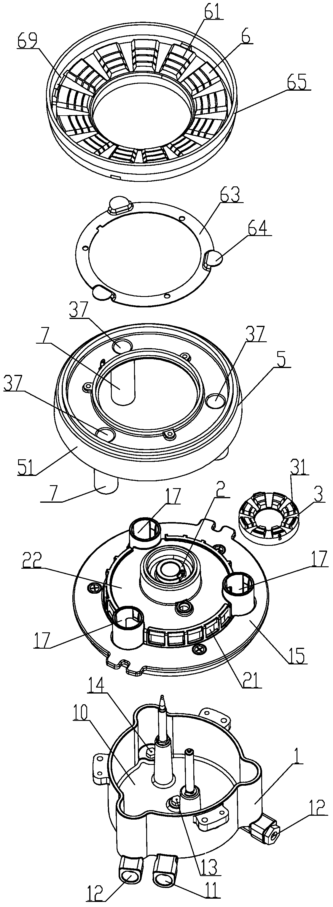
[0036] Burner base 1, a base cavity 10 is provided inside the burner base 1, an inner ring air intake channel 11 and an outer ring air intake channel 12 are provided on the burner base 1, and one end of the inner ring air intake channel 11 communicates with the base cavity 10 An inner ring nozzle 13 is provided, and an outer ring nozzle 14 is provided at the end of the outer ring air intake channel 12 communicating with the base cavity 10; the inner ring air intake channel 11 and the outer ring air intake channel 12 have a horizontal section, through which the air is fed in;

[0037] Base upper cover 15, which is located on the burner base 1 to cover the base cavity 10, the base upper cover 15 is provided with an air filling hol...


PUM


Abstract

The invention relates to an upper air feeding burner. The upper air feeding burner is characterized by comprising a burner base, an upper base cover, an inner burner cap seat, an inner burner cap, an inner injection pipe, an outer burner cap seat, an outer burner cap and an outer injection pipe; a base cavity is formed in the burner base, an inner ring air inflow channel and an outer ring air inflow channel are arranged in the burner base, the inner ring air inflow channel is provided with an inner ring nozzle, and the outer ring air inflow channel is provided with an outer ring nozzle; an air supplementing inlet is formed in the upper base cover; the inner burner cap seat is arranged on the upper base cover; an inner burner cap hole is formed in the inner burner cap and an inner ring gas channel is defined by the inner burner cap and the inner burner cap seat; one end of the inner injection pipe is opposite to the inner ring nozzle and the other end of the inner injection pipe is communicated with the inner ring gas channel; the outer burner cap seat is arranged on the upper base cover; an outer burner cap hole is formed in the outer burner cap, an outer ring gas channel is defined by the outer burner cap and the outer burner cap seat, and an air supplementing inflow channel is defined between the upper base cover and the outer burner cap seat; and one end of the outer injection pipe is opposite to the outer ring nozzle and the other end of the outer injection pipe is communicated with the outer ring gas channel. The upper air feeding burner is simple in structure and high in burning efficiency.

Description

【Technical field】 [0001] The invention relates to an upward air intake burner. 【Background technique】 [0002] After the upper air inlet burner is installed, there is no need to open ventilation holes on the burning appliance, so that cockroaches and mice are not easy to enter the burning appliance, so the interior of the burning appliance is relatively clean, and cleaning and maintenance are more convenient. The upward air intake burner is also widely used, but the upward air intake burner also has its disadvantages. The main reason is that the air supply is insufficient, which may easily lead to incomplete combustion of the gas. In order to supplement enough air, some burners have an air channel that is easy to allow soup, etc. to flow into it. into the burner. 【Content of invention】 [0003] The purpose of the present invention is to overcome the deficiencies of the prior art and provide an upward air-intake burner with simple structure, sufficient air supply, complete...

Claims


Application Information

Patent Timeline
Patent Type & Authority Patents(China)
IPC IPC(8): F23D14/04F23D14/46F23D14/48F23D14/64
Inventor 郭力李建国王东云
Owner CHINABEST HOME APPLIANCE
Why Eureka
Try Eureka