Ferrograph making oil flow speed control system

A flow rate control and oil technology, which is applied in the direction of control/regulation system, non-electric variable control, and simultaneous control of multiple variables, etc., can solve the problems of changing action time, insensitive response, flow rate fluctuations, etc., and achieve the goal of reducing fluctuations Range, solve the effect of output instability

Active Publication Date: 2016-02-24
SHENZHEN YATEKS OPTICAL ELECTRONICS TECH CO LTD
View PDF5 Cites 2 Cited by
  • Summary
  • Abstract
  • Description
  • Claims
  • Application Information

AI Technical Summary

Problems solved by technology

[0003] The piston-type cylinder has a stable air outlet, and the flow rate and pressure are mainly controlled by controlling the stroke speed, but the response is not sensitive because the stroke must be completed before the control can continue, and the sealing ring expands and contracts when the piston is hot or cold, which will cause blockage or oil leakage , which will cause the production of ferrograms to fail
[0004] The micro vacuum pump mainly controls the flow rate and pressure by controlling the duty cycle of the driven PWM (PulseWidthModulation, pulse width modulation). The frequency affects the gas volume output.

Method used


Image

  • Ferrograph making oil flow speed control system
  • Ferrograph making oil flow speed control system
  • Ferrograph making oil flow speed control system

Examples


Embodiment 1

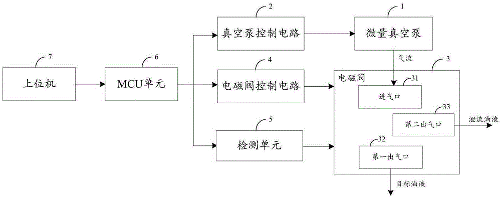
[0034] Such as figure 1 As shown, the ferrographic production oil flow rate control system includes a micro vacuum pump 1, a vacuum pump control circuit 2, a solenoid valve 3, a solenoid valve control circuit 4, a detection unit 5, an MCU unit 6, and a host computer 7, wherein:

[0035] The micro vacuum pump 1 is connected with the MCU unit 6 through the vacuum pump control circuit 2 as an oil source; the solenoid valve 3 is connected with the MCU unit 6 through the solenoid valve control circuit 4 to receive the control signal of the MCU unit 6, and the solenoid valve 3 is also connected with the micro The vacuum pump 1 is connected, and the oil source is shunted through the control signal; the detection unit 5 is respectively connected with the solenoid valve 3 and the MCU unit 6, and is used to detect the oil information of the solenoid valve 3, and transmit the detection result to the MCU unit 6 , can feed back the oil information of the solenoid valve 3 to the MCU unit 6 ...

Embodiment 2

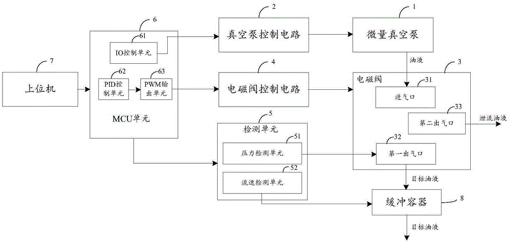
[0042] Such as figure 2 As shown, the ferrography production oil flow rate control system includes a micro vacuum pump 1, a vacuum pump control circuit 2, a solenoid valve 3, a solenoid valve control circuit 4, a detection unit 5, an MCU unit 6 and a host computer 7.

[0043] In this embodiment, on the basis of embodiment 1, a buffer container 8, a pressure detection unit 51 and a flow rate detection unit 52 are added, and the same parts as those in the embodiment are not repeated here.

[0044] Further, the oil flow rate control system for ferrography further includes a buffer container 8 connected to the first air outlet 32 ​​for buffering and outputting the target oil. The use of the buffer container 8 makes it easier for the electromagnetic valve 3 to adjust the fluctuation range.

[0045]Further, the detection unit 5 includes: a pressure detection unit 51 and a flow rate detection unit 52, the pressure detection unit 51 is respectively connected with the first air outle...

Embodiment 3

[0049] Such as image 3 As shown, the oil flow rate control system for ferrography production includes micro vacuum pump 1, vacuum pump control circuit 2, solenoid valve 3, solenoid valve control circuit 4, detection unit 5, MCU unit 6, host computer 7 and buffer container 8.

[0050] In this embodiment, an IO control unit 61 , a PID control unit 62 and a PWM output unit 63 are added on the basis of Embodiment 2, and the same parts as those in Embodiment 2 will not be repeated here.

[0051] Further, the MCU unit 6 includes: an IO control unit 61 , the IO control unit 61 is connected with the vacuum pump control circuit 2 , and is used to realize the IO control of the micro vacuum pump 1 by the MCU unit 6 .

[0052] Further, the MCU unit 6 also includes a PID control unit 62 and a PWM output unit 63, the PID control unit 62 is connected with the PWM output unit 63 for adjusting the PWM signal output by the PWM output unit 63; the PWM output unit 63 is also connected with the s...


PUM


Abstract

The invention relates to a ferrograph making oil flow speed control system, belonging to the fluid drive filed. The system comprises a micro vacuum pump, a vacuum pump control circuit, a solenoid valve, a solenoid valve control circuit, a detection unit, an MCU unit and a host computer, wherein the micro vacuum pump is connected with the vacuum pump control circuit via the MCU unit, the solenoid valve is connected with the solenoid valve control circuit via the MCU unit, the detection unit is connected with both the solenoid valve and the MCU unit, and the MCU unit is connected with the host computer. When output of the micro vacuum pump fluctuates widely, the ferrograph making oil flow speed control system can make timely feedback, and adjust output of the micro vacuum pump and branches of the solenoid valve timely to decrease fluctuation and solve the problems of unstable output and high failure rate of an oil source.

Description

【Technical field】 [0001] The invention relates to the field of fluid drive, in particular to an oil flow rate control system for ferrography production. 【Background technique】 [0002] At present, piston cylinders or micro-vacuum pumps are mainly used in ferrography production systems to control the flow rate and pressure of oil. [0003] The piston-type cylinder has a stable air outlet, and the flow rate and pressure are mainly controlled by controlling the stroke speed, but the response is not sensitive because the stroke must be completed before the control can continue, and the sealing ring expands and contracts when the piston is hot or cold, which will cause blockage or oil leakage , which will cause the production of ferrograms to fail. [0004] The micro vacuum pump mainly controls the flow rate and pressure by controlling the duty ratio of the driven PWM (PulseWidthModulation, pulse width modulation). The frequency affects the air volume output. When the valve is ...

Claims


Application Information

Patent Timeline
IPC IPC(8): G05D27/02
CPCG05D27/02
Inventor 刘依霞陈明李春龙汪甜
Owner SHENZHEN YATEKS OPTICAL ELECTRONICS TECH CO LTD
Why Eureka
Try Eureka