
Quantum secrete key dynamic distribution management method and system

A quantum key distribution and quantum key technology, applied in the field of management methods and systems for the dynamic distribution of quantum keys, can solve the problems of different use speeds, inability to meet systems and methods, etc., and achieve good practicability and high management efficiency. Effect

Active Publication Date: 2016-02-24
ANHUI QASKY QUANTUM SCI & TECH CO LTD
View PDF5 Cites 32 Cited by
  • Summary
  • Abstract
  • Description
  • Claims
  • Application Information

AI Technical Summary

Problems solved by technology

Different key users have different needs for keys and use speeds. During the key use process, it must be ensured that each user pair has a basic usable key, and the user pairs that meet more key requirements, However, there are no systems and methods that can meet this requirement on the market and in the prior art

Method used


Image

  • Quantum secrete key dynamic distribution management method and system
  • Quantum secrete key dynamic distribution management method and system
  • Quantum secrete key dynamic distribution management method and system

Examples


Embodiment 1

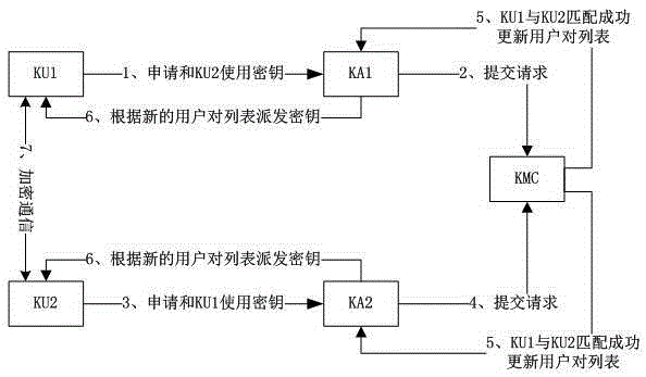
[0035] see figure 1 , image 3 with Figure 4 , the management method for the dynamic distribution of quantum keys, including KMC and two security controlled areas, when one security controlled area is the local end, the other security controlled area is the opposite end; KMC is connected through the key control channel Between two security controlled areas; the local end includes quantum key distribution terminal QKD1, key service agent KA1, and key user KU1; the opposite end includes quantum key distribution terminal QKD2, key service agent KA2 , the user KU2 of the key; including the following steps:

[0036] (1) KU1 sends a request to KA1 to apply for communication with KU2 using a key;

[0037] (2) KA1 submits KU1's request to KMC;

[0038] (3) KU2 sends a request to KA2 to apply for communication with KU1 using a key;

[0039] (4) KA2 submits KU2's request to KMC;

[0040] (5) KMC makes KU1 and KU2 match successfully through the request, forms a user pair and puts ...

Embodiment 2

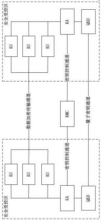
[0047] see figure 2 , the management system for the dynamic distribution of quantum keys includes KMC and two security controlled areas, KMC is connected between the two security controlled areas through the key control channel; when one security controlled area is the local end, the other The security-controlled area is the opposite end; the communication between users in the security-controlled area does not need to be encrypted, and the user communication between two different security-controlled areas uses quantum keys for encryption protection; the security-controlled area includes QKD, KA, KU; QKD is a quantum key distribution terminal, which is used to generate a symmetrical quantum key between the local end and the peer end; KA is a key service agent, which is used to store the quantum key generated by the local QKD , distribution and management; KU is the user of the key, and is used to read the quantum key from the KA at the local end; KMC is the key management cent...


PUM


Abstract

The invention discloses a quantum secrete key dynamic distribution management method, and the method comprises the steps that UU1 sends a request to KA1, so as to apply to carry out communication with KU2 through a secrete key; KA1 submits the request of KU1 to KMC; KU2 sends a request to KA2, so as to apply to carry out communication with KU2 through a secrete key; KA2 submits the request of KU2 to KMC; KMC passes the request, and enables the matching of KU1 and KU2 to be successfully, thereby forming a user pair which is put in a user pair list, and forming an updated user pair list; KMC enables the updated user pair list to be supplied to KA1 and KA2; KA1 and KA2 distributes the secrete keys according to the updated user pair list, and respectively provides secrete keys for KU1 and KU2; and KU1 and KU2 carry out data encryption communication through the obtained secrete keys. The invention also discloses a quantum secrete key dynamic distribution management system. The method and system are high in management efficiency of quantum secrete keys, and are good in practicality.

Description

technical field [0001] The invention relates to a management method and system of a quantum key pool, in particular to a management method and system for dynamic distribution of quantum keys. Background technique [0002] In the process of symmetric key distribution, key management is difficult, especially when there are many key users. In the key distribution with key pool, the key is written into the key pool, and The key pool is read and then distributed to key users. This requires a unified scheduling of the key pool to ensure the balanced use of multi-user keys. In the quantum key distribution network, the key is distributed to two places by the quantum key distribution device, and the two places respectively establish buffer key pools. When the key users use the key, they read the key from the key pool at both ends. key. Different key users have different needs for keys and use speeds. During the key use process, it must be ensured that each user pair has a basic usa...

Claims


Application Information

Patent Timeline
Patent Type & Authority Applications(China)
IPC IPC(8): H04L9/08
CPCH04L9/083H04L9/0852
Inventor 苗春华王剑锋尹凯王立霞王雨张奇赵义博
Owner ANHUI QASKY QUANTUM SCI & TECH CO LTD
Learn More