Shearing mechanism of injection syringe

A technology for a syringe and a body, which is applied in the field of syringe processing, can solve the problems of hidden danger of hand puncture, health hazards of medical staff and the like

Inactive Publication Date: 2016-03-02
WUXI ANZHIZHUO MEDICAL ROBOT CO LTD
View PDF7 Cites 2 Cited by
  • Summary
  • Abstract
  • Description
  • Claims
  • Application Information

AI Technical Summary

Problems solved by technology

In the process of dismantling the needle, the medical staff has a safety hazard of pricking their hands
And when the drug is toxic, it will also cause health hazards to medical staff

Method used


Image

  • Shearing mechanism of injection syringe
  • Shearing mechanism of injection syringe

Examples


Embodiment Construction

[0013] Specific embodiments of the present invention are described in detail below, but it should be understood that the protection scope of the present invention is not limited by the specific embodiments.

[0014] Unless expressly stated otherwise, throughout the specification and claims, the term "comprise" or variations thereof such as "includes" or "includes" and the like will be understood to include the stated elements or constituents, and not Other elements or other components are not excluded.

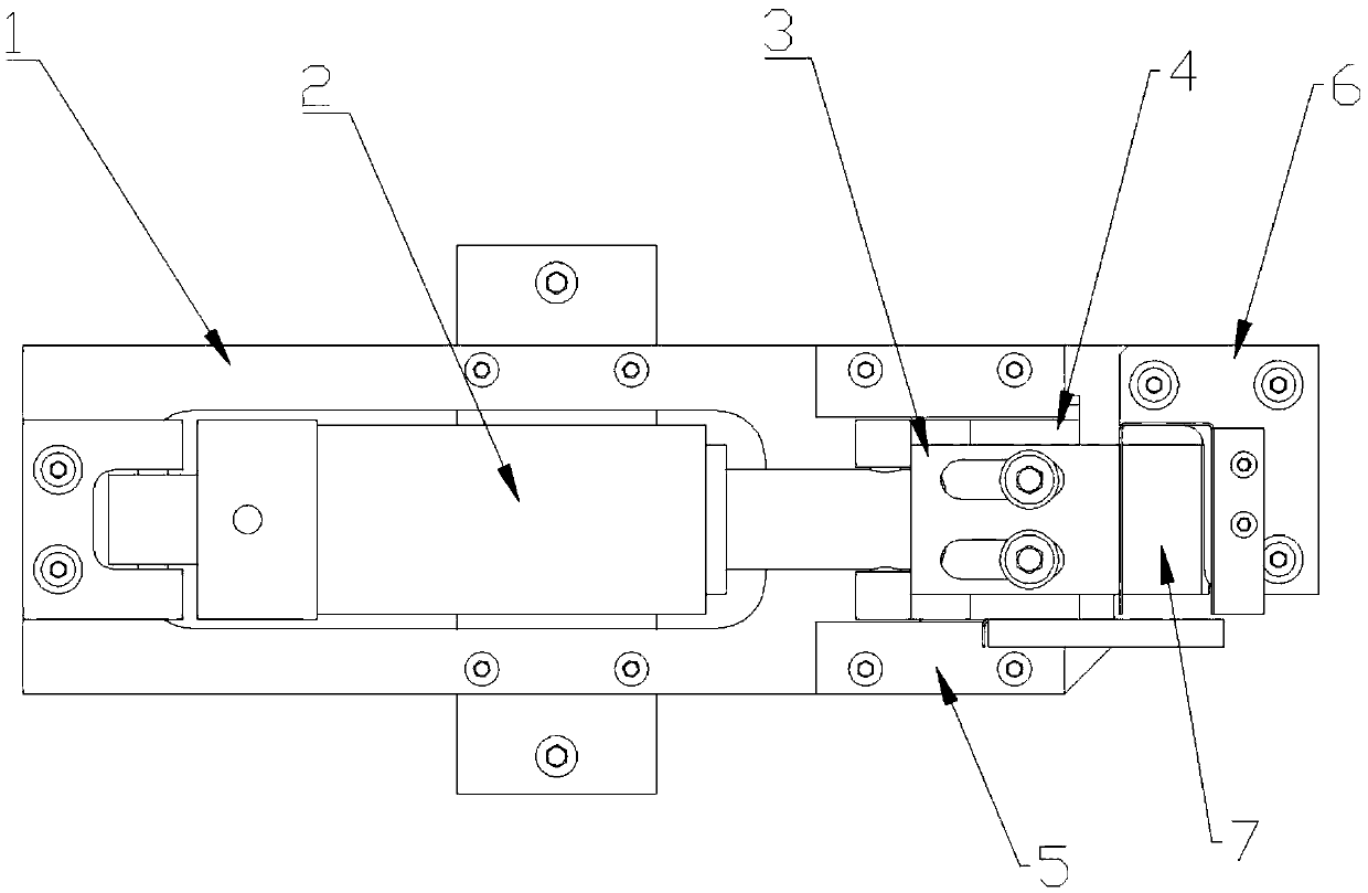
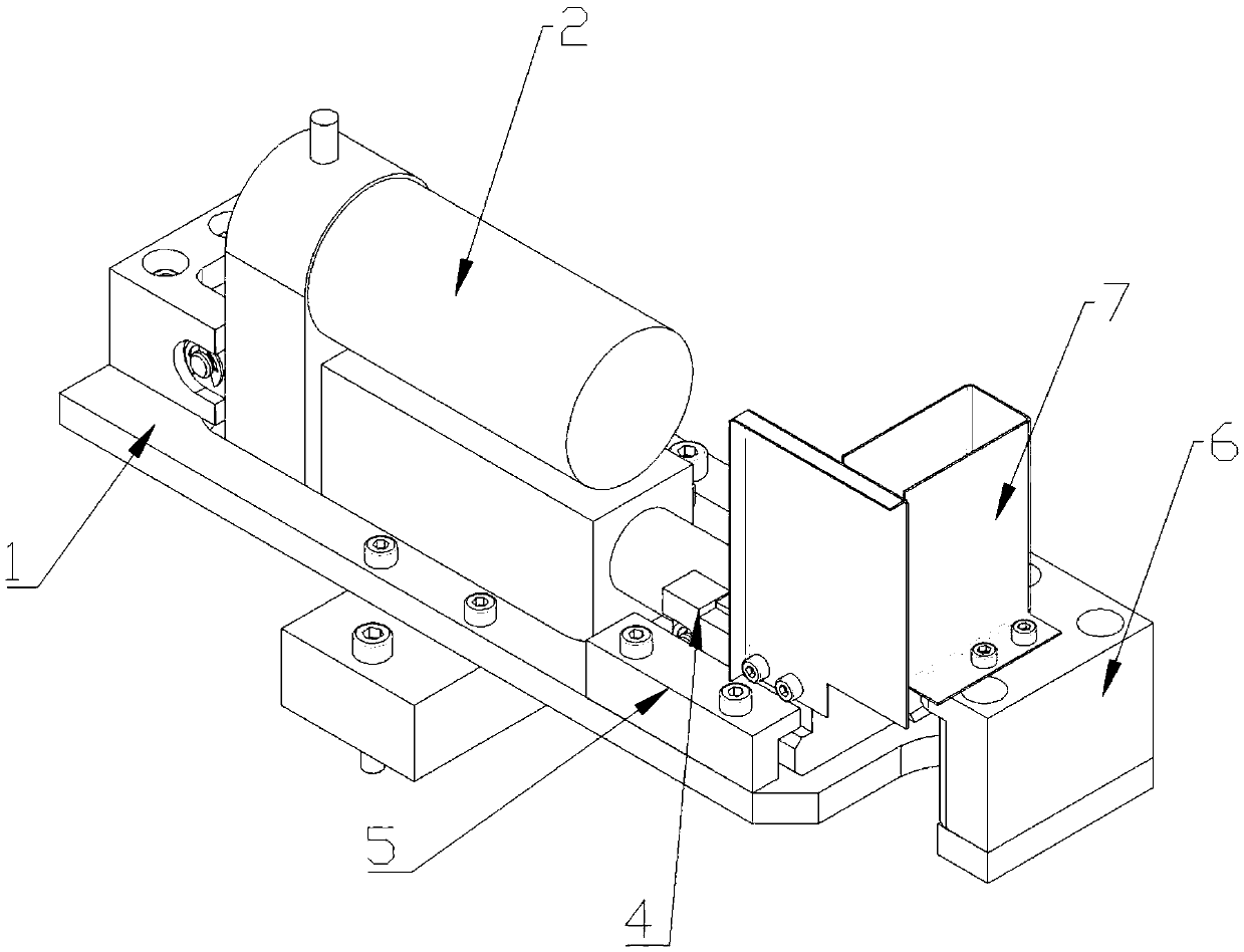
[0015] Such as Figure 1-2 As shown, the syringe shearing mechanism includes: a body 1, an electric push rod 2, a blade 3, a slider 4, a slide rail 5, a bracket 6, and an "L"-shaped guard plate 7; the body 1 is provided with an electric push rod 2 , the slider 4 is arranged on the slide rail 5, the slider 4 is provided with the blade 3, the bracket 6 is arranged in the moving direction of the blade 3, and the bracket 6 is provided with an "L" shaped guard plate 7 , the "L" s...


PUM


Abstract

The invention discloses a shearing mechanism of an injection syringe. A mechanism body is provided with an electric push rod, a slider is arranged on slide rails, a blade is arranged on the slider, and a bracket is arranged in the movement direction of the blade, and is provided with an L-shaped protection board. When moving forwards, the electric push rod contacts the slider and drives the blade to move forwards, and the blade and the L-shaped protection board form a shore object placement space. According to the invention, the shearing mechanism replaces the manual operation, so that the potential safety hazard that hands are pricked or a person suffers from drug poisoning existing when the person detaches the syringe needle is avoided.

Description

Technical field: [0001] The invention belongs to the field of syringe processing, in particular to a syringe cutting mechanism. Background technique: [0002] At present, in hospitals, when the liquid preparation is completed, according to the requirements, the syringe needs to be destroyed before it can be discarded to prevent secondary use. The manual mode that the hospital adopts now disassembles the syringe and the needle, and sorts and discards. In the process of dismantling the needle, the medical staff has a potential safety hazard of pricking their hands. And when the drug is toxic, it will also cause health hazards to medical staff. [0003] The information disclosed in this Background section is only for enhancing the understanding of the general background of the present invention and should not be taken as an acknowledgment or any form of suggestion that the information constitutes the prior art that is already known to those skilled in the art. Invention con...

Claims


Application Information

Patent Timeline
Patent Type & Authority Applications(China)
IPC IPC(8): A61M5/32B21F11/00
Inventor 王海涛刘文彦
Owner WUXI ANZHIZHUO MEDICAL ROBOT CO LTD
Why Eureka
Try Eureka