A cutting knife wheel for fragile materials

A technology of brittle materials and cutting knives, which is applied in glass cutting devices, stone processing tools, stone processing equipment, etc., can solve problems such as inability to effectively control glass bifurcations, disc knives are difficult to cut into the glass, and avoid glass The effect of bifurcation and splitting

Inactive Publication Date: 2016-03-02
孙春雨
View PDF7 Cites 6 Cited by
  • Summary
  • Abstract
  • Description
  • Claims
  • Application Information

AI Technical Summary

Problems solved by technology

It is difficult for the disc knife to cut into the inside of the glass
The micro-toothed cutter wheel has a single micro-tooth on one cutter wheel. This kind of micro-toothed cutter wheel includes trapezoidal, inverted trapezoidal, triangular, and arc-shaped micro-toothed cutter wheels mentioned in patent document ZL200410104603.2. The toothed cutter wheel can cut into the glass, but after cutting into the glass, it cannot effectively control the glass bifurcation or glass cracking

Method used


Image

  • A cutting knife wheel for fragile materials
  • A cutting knife wheel for fragile materials
  • A cutting knife wheel for fragile materials

Examples


no. 1 Embodiment

[0064] The first specific embodiment (the first cutter wheel):

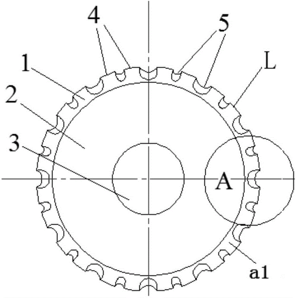
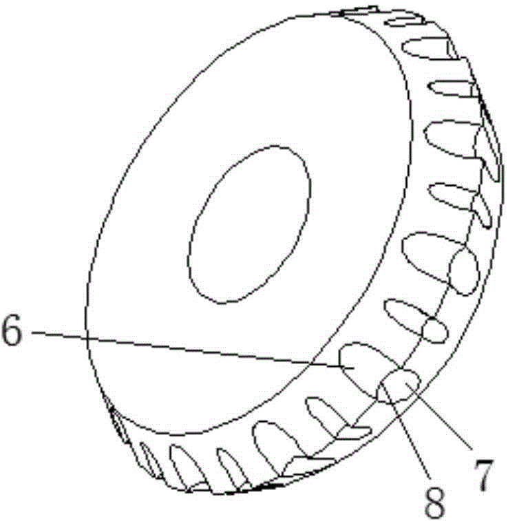
[0065] As shown in Fig. 1 (a), Fig. 1 (b), and Fig. 1 (c), the first cutting wheel includes two kinds of concave structures 5 with different sizes, which are respectively the first concave structure 51 and the second concave structure 52 The bottoms of the first concave structure 51 and the second concave structure 52 are both provided with a V-shaped cutting edge 8 formed by the first concave surface 6 , the second concave surface 7 and the curved section. The first recessed structures 51 and the second recessed structures 52 are alternately arranged at intervals. Among them, the first concave structure 51 and the second concave structure 52 can be connected by a smooth transition of a circular arc between the position close to the circular disk surface 2 and the first curved surface a1 and the second curved surface a2; and the first concave structure 51 and The junction between the second concave structure 52 ...

no. 2 Embodiment

[0067] The second specific embodiment (the second cutter wheel):

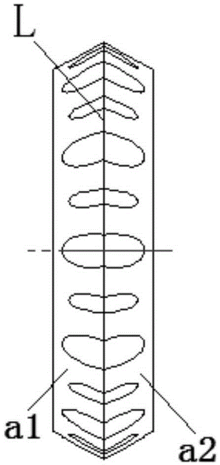
[0068] As shown in Fig. 2 (a), Fig. 2 (b), at least one third curved surface a3 can also be provided between one side of the outer edge ridge line L of the second cutting wheel and the first curved surface a1, and the outer edge edge At least one fourth curved surface a4 may also be provided between the other side of the line L and the second curved surface a2.

no. 3 Embodiment

[0069] The third specific embodiment (the third cutter wheel):

[0070] As shown in Fig. 3(a) and Fig. 3(b), the third cutting wheel has several different types of concave structures 5, for example. Except the concave structure 5 that is provided with on the first cutter wheel, also have the concave structure 5 of multiple shapes such as trapezoid, inverted trapezoid, triangle and circular arc, not describe one by one here, and the concave structure of various shapes and sizes 5 can be provided with a V-shaped cutting edge 8, and those of ordinary skill in the art should understand that the size changes, structural changes, opening size changes, and bottom changes of the recessed structure 5 should all be covered by the scope of the technical solution claimed by the present invention. among.


PUM

PropertyMeasurementUnit
diameteraaaaaaaaaa
thicknessaaaaaaaaaa
thicknessaaaaaaaaaa

Abstract

The invention provides a cutting knife wheel for fragile materials. The cutting knife wheel comprises a V-shaped cutting blade portion consisting of a first curved surface, a second curved surface and an outer edge ridge, a round disc surface and a central shaft hole. The outer edge ridge of the V-shaped cutting blade portion circumferentially has cutting blades and recessed structures distributed alternately. The outer edge ridge circumferentially has recessed structures of at least two different shapes and sizes, and the recessed structures are arranged in order or without order along the outer edge ridge. A first cutting tip and a second cutting tip are formed between each recessed structure and the corresponding two adjacent cutting blades. The first cutting tips and the second cutting tips on the two sides of at least one part of the recessed structures are used for cutting in glass and forming crack lines and the first cutting tips and the second cutting tips on the two sides of at least one part of the recessed structures are used for controlling the extension of the crack lines in the glass and preventing forking and over-cracking of the glass. The cutting knife wheel can effectively control the forking and over-cracking of fragile materials and is especially suitable for tempered glass.

Description

technical field [0001] The invention relates to a cutting tool, in particular to a cutting wheel suitable for brittle materials, wherein the brittle materials include glass, ceramics, sapphire, silicon chips and semiconductor materials. Background technique [0002] With the advancement of technology, many fields require glass to be thin and hard, especially the touch screen industry. The glass used in the touch screen industry generally requires the glass to be thin and have very high strength and hardness. The most important thing is that there is a chemically strengthened layer tens of microns thick on the surface of the glass, which greatly increases the difficulty of cutting. Moreover, the thickness of the commonly used strengthened glass is roughly 1.1mm, 0.7mm, 0.55mm, and 0.4mm. The strengthened glass with a thickness of less than 1mm is prone to cracking and bifurcation during cutting, and the splitting time is particularly difficult to control. [0003] Cutting cu...

Claims


Application Information

Patent Timeline
Patent Type & Authority Applications(China)
IPC IPC(8): B28D1/24C03B33/10
Inventor 孙春雨
Owner 孙春雨
Why Eureka
Try Eureka