Thread cutting device for sewing machine

A sewing machine and thread cutting technology, which is applied to the thread cutting mechanism, sewing machine components, sewing equipment and other directions in the sewing machine, can solve the problems of complex structure, affecting product appearance and sewing quality, and low production efficiency.

Inactive Publication Date: 2018-11-02
林泽贤
View PDF5 Cites 3 Cited by
  • Summary
  • Abstract
  • Description
  • Claims
  • Application Information

AI Technical Summary

Problems solved by technology

[0003] The structure of the existing sewing machine thread cutting device is relatively complicated. It is necessary to pick out the sewing thread of the machine needle with the thread hooking structure first, and then clamp the sewing thread to the cutter through the thread clamping structure for thread cutting. In the process of thread clamping and thread clamping, the sewing thread will be stretched virtually. After the thread trimming is completed, a long thread end will be left on the sewing material. Later, the thread end needs to be manually trimmed with scissors to maintain the aesthetics

Method used


Image

  • Thread cutting device for sewing machine
  • Thread cutting device for sewing machine
  • Thread cutting device for sewing machine

Examples


Embodiment 1

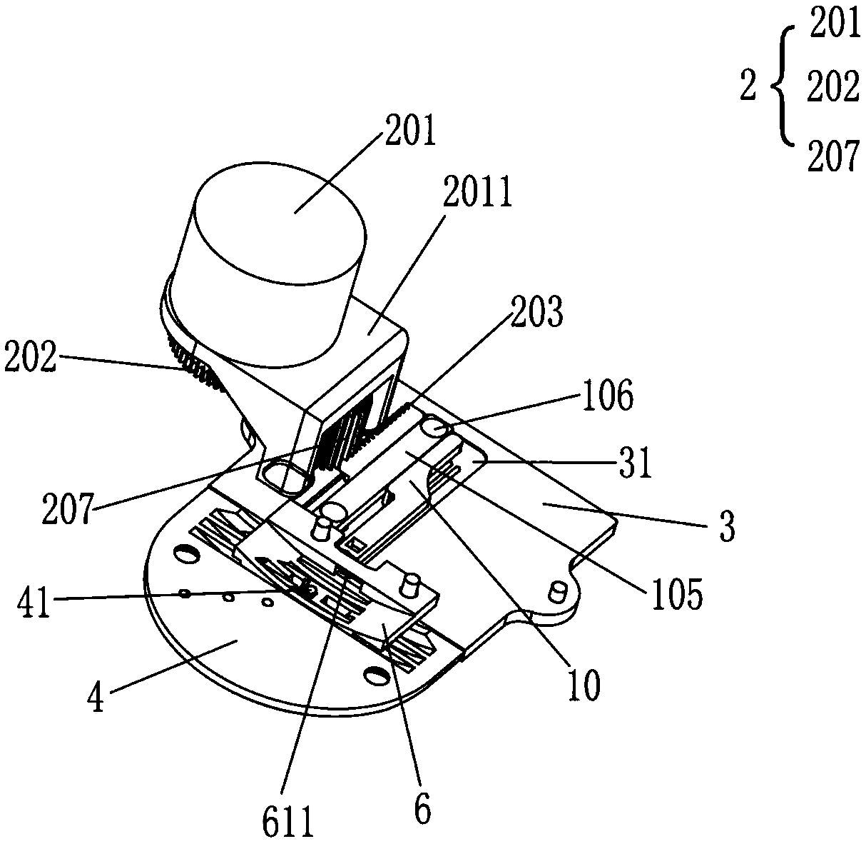
[0043] Such as figure 2 , image 3 , Image 6 with Figure 7 As shown, the electric heat cutting assembly 1 includes a push plate 10, an electric heat cutter 11 and an electric heater for heating the electric heat cutter 11, the push plate 10 also includes a connecting arm 101, the connecting arm 101 and the driving arm 102 are arranged in parallel, and the thread cutting arm 103 is connected to one side edge of connecting arm 101, and is set toward the extension direction of connecting arm 101, because the size of needle plate 4 is smaller, setting tangent arm 103 is longer than driving arm 102—in order to carry out structure during the movement process of pushing plate 10 Dodging is also convenient for the power cord of the electric heater to be arranged. The second is to simplify the structure; the electric thermal cutter 11 is located at the bottom of the thread cutting arm 103, and the wire hook groove 1031 is arranged at the front end of the thread cutting arm 103. Th...

Embodiment 2

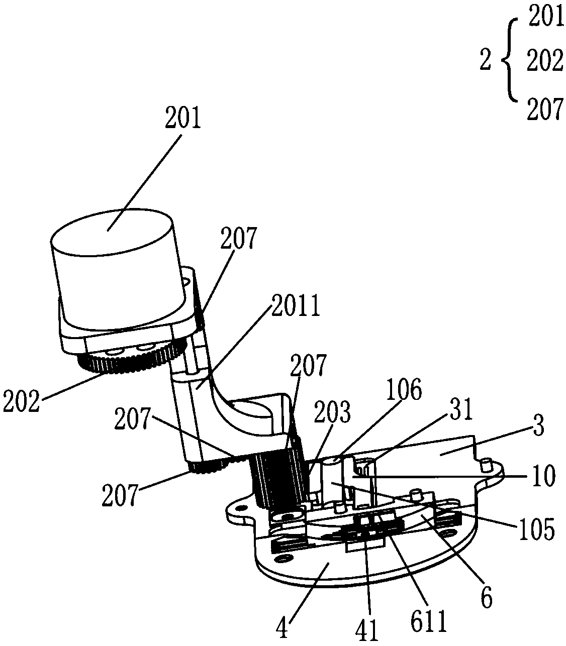
[0049] The difference between this embodiment and Embodiment 1 is that, as Figure 4 , Image 6 with Figure 7 As shown, the driving device 2 includes an electromagnet 204, a pull rod 205 and a transmission rod 206, the pull rod 205 is connected to the electromagnet 204, and a spring 2051 is sleeved on the pull rod 205, and the two ends of the spring 2051 abut against the electromagnet 204 and the transmission rod respectively 206, one end of the transmission rod 206 is connected to the pull rod 205, and the other end is connected to the driving arm 102. Specifically, when the thread is cut, the electromagnet 204 is energized, and the electromagnet 204 generates magnetism after being energized, and the pull rod 205 is close to the electromagnet 204 under the action of magnetic force. movement, the spring 2051 is compressed, driving the transmission rod 206 to move towards the direction close to the electromagnet 204, and then driving the push plate 10 to move, so that the thr...

Embodiment 3

[0051] The difference between this embodiment and Embodiment 1 is that, as Figure 5 , Image 6 with Figure 7 As shown, the electric heating thread cutting assembly 1 is entirely arranged on the needle plate 4, which is beneficial to simplify the overall structure of the sewing machine. The needle plate 4 is provided with a chute 31 for the sliding of the push plate 10, and the two ends of the limit plate 105 pass through the limit column 106. It is fixed in the chute 31. Specifically, the needle plate 4 includes a notch part and a mounting part. The notch part has an arc surface matching the concave arc surface of the feeding dog 6, and the feeding dog notch 42 is arranged on the needle. The notch of the plate 4 matches the teeth 63 of the feed dog 6, the pinhole 41 is set on the notch of the needle plate 4, and the installation part is arranged flat. The thread cutting arm 103 on the plate 10 is driven by the driving device 2 to move towards the needle hole 41 in the notc...


PUM


Abstract

The invention relates to the technical field of sewing machines, and discloses a thread cutting device for a sewing machine. An electric heating cutting knife on a push plate is driven by a driving device to move on a needle plate, so that a sewing thread is subjected to hot melting and cut off, the sewing thread does not need to be lengthened during the cutting, the electric heating cutting knifeis directly attached to the position of a needle hole to perform hot melting and cut off a sewing upper thread a sewing base thread, short thread residues are implemented, the short thread residues remain in the inner surface of a sewing material, and the thread residues do not need to be manually cut by a pair of scissors subsequently. At the same time, since the thread residues of the sewing upper thread and the sewing base thread are short, a bird nest prevention effect can be effectively achieved, and the sewing material attractiveness is maintained. In addition, the sewing thread is cutby using the electric heating cutting knife, the sewing thread can be instantly subjected to hot melting and cut off under the action of the high-temperature electric heating cutting knife, a hot meltthread residue similar to a mushroom head is formed at the end of the thread, so that the thread residue end can be prevented from branching, and the end of the thread residue of the upper thread canbe prevented from falling off from a machine needle.

Description

technical field [0001] The invention relates to the technical field of sewing machines, in particular to a thread cutting device for sewing machines. Background technique [0002] A sewing machine is a machine that uses one or more sewing threads to form one or more stitches on the sewing material to interweave or sew one or more layers of sewing material. The sewing machine can sew fabrics such as cotton, hemp, silk, wool, and artificial fibers, and products such as leather, plastics, and paper. The stitches that are sewn are neat and beautiful, flat and firm, and the sewing speed is fast and easy to use. [0003] The structure of the existing sewing machine thread cutting device is relatively complicated. It is necessary to pick out the sewing thread of the machine needle with the thread hooking structure first, and then clamp the sewing thread to the cutter through the thread clamping structure for thread cutting. In the process of thread clamping and thread clamping, th...

Claims


Application Information

Patent Timeline
IPC IPC(8): D05B65/00D05B65/06
CPCD05B65/006D05B65/06
Inventor 林泽贤
Owner 林泽贤
Why Eureka
Try Eureka