Hull structure with underwater appendage

A technology of underwater attachment and hull, applied in the field of high-performance ships, can solve problems such as hindering the development of high-performance ships, reducing the comfort of passengers on board, and prone to violent turbulence, etc., to improve propulsion efficiency, improve maneuverability, and facilitate installation. and maintenance effect

Inactive Publication Date: 2016-03-02
INST OF IND TECH GUANGZHOU & CHINESE ACADEMY OF SCI
View PDF8 Cites 8 Cited by
  • Summary
  • Abstract
  • Description
  • Claims
  • Application Information

AI Technical Summary

Problems solved by technology

However, because the underwater appendage of a high-performance ship is disturbed by waves during driving, the hull vibrates greatly, and it is prone to severe bumping and shaking. The comfort of passengers on board is greatly reduced, which hinders the underwater Application and development of high-performance ship with attached structure

Method used


Image

  • Hull structure with underwater appendage
  • Hull structure with underwater appendage
  • Hull structure with underwater appendage

Examples


Embodiment 1

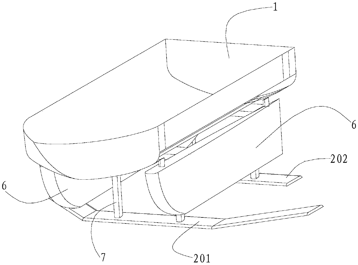
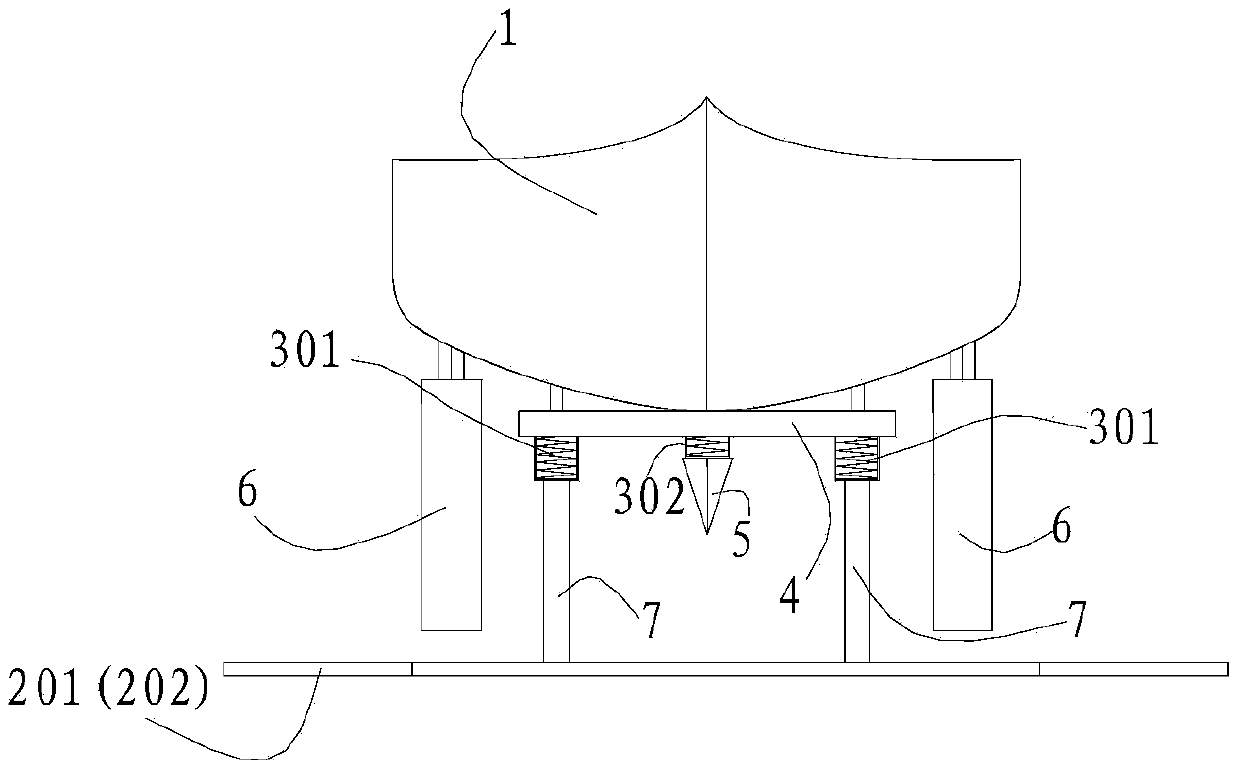
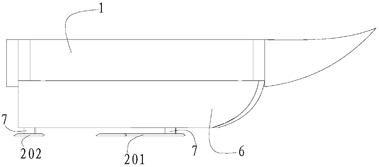
[0053] Such as Figure 1-10 As shown, a hull structure with an underwater appendage includes a hull 1 and an underwater appendage arranged below the hull 1, and a suspension device is arranged between the hull 1 and the underwater appendage. In this embodiment, the underwater appendage includes an appendage, a connecting shaft 203 connecting the appendage and the suspension device 301, wherein the appendage includes a front hydrofoil 201 arranged below the middle of the hull 1 and a hydrofoil 201 arranged below the tail of the hull 1. The rear hydrofoil 202 and the front hydrofoil 201 are swept-back hydrofoils, and the front hydrofoil 201 is longer than the rear hydrofoil 202 . The connecting shaft 203 is sleeved with a streamlined pillar 7 that can rotate relative to the connecting shaft 203 . The structure is simple, adopting the structural form of double hydrofoils, and the arrangement form is an aircraft layout, which improves the maneuverability and operability of the hyd...

Embodiment 2

[0060] Such as Figure 12 As shown, the difference between this embodiment and Embodiment 1 lies in the installation position of the chassis 4: the hull 1 is arranged on the suspension device 301, the chassis 4 is arranged below the suspension device 301, and the front hydrofoil 201 and the rear hydrofoil 202 are arranged On chassis 4. The front hydrofoil 201, the rear hydrofoil 202, the suspension device 3, and the chassis 4 form a modular structure that can be used to place and support the hull 1. In application, the hull 1 only needs to be placed on the suspension device 301 and supported by the chassis 4. The hull 1 can be transformed into a hydrofoil boat with fast speed, good seakeeping performance and high comfort for passengers in the hull, which is convenient for popularization of the hydrofoil boat. In addition, installing the chassis 4 under the hull 1 is more convenient for the installation and maintenance of the hydrofoil structure 2 and auxiliary facilities.

...

Embodiment 3

[0063] Such as Figure 13-16 As shown, the difference between this embodiment and Embodiment 1 is that no flat buoy 6 is set in this embodiment, but a triangular buoy 8 arranged along the direction of the hull is symmetrically arranged on both sides of the hull 1, and the triangular buoy 8 of the triangular buoy The section is triangular, and the section of the triangular buoy 8 and the hull 1 is trapezoidal, and only a single hydrofoil 204 is provided in this embodiment. The triangular buoy 8 presents an airfoil feature with a certain length along the direction of the hull, which can produce ground effect when the ship is sailing, which increases the lift of the ship, reduces the draft of the ship, and then reduces the resistance of the ship and improves the performance of the ship. For propulsion efficiency, the reduction in draft also raises the hull 1, which in turn reduces the action of waves.


PUM


Abstract

A hull structure with an underwater appendage comprises an underwater appendage structure arranged below the hull; a suspension is arranged between the underwater appendage structure and the hull; the hull structure arranges the suspension between the hull and the underwater appendage structure so as to buffer the wave impact load on the underwater appendage structure; the suspension can attenuate impact vibrations, can weaken refloating motions caused by posture adjustment, and comprises an elastic piece, a damper and a guide mechanism respectively providing buffering, damping and force transmission effects; the underwater appendage structure receives the impact transferred by the waves; the guide mechanism transfers force and moment between the underwater appendage structure and the bottom of the hull; the elastic piece can be deformed; the damper can provide damping effect for the elastic piece so as to prevent the elastic piece from swinging back and forth, so the impact on the bottom of the hull can be greatly reduced, thus improving hull sea-keeping, and improving passenger comfort level on the hull.

Description

technical field [0001] The invention mainly relates to the technical field of high-performance ships. Background technique [0002] High-performance ships are one of the development directions of ships in the future, and their high-speed, seakeeping and other performances have great advantages over traditional ships. Among them, the existing high-performance ships mainly realize their high-speed performance by setting up underwater appendage structures on the ship. Using the lift or buoyancy of the underwater appendages, the main body of the ship is lifted above the water surface, which greatly reduces the impact on the main body of the ship. The resistance of the water and the impact of the waves, thus improving the speed and seakeeping of the ship. However, because the underwater appendage of a high-performance ship is disturbed by waves during driving, the hull vibrates greatly, and it is prone to severe bumping and shaking. The comfort of passengers on board is greatly ...

Claims


Application Information

Patent Timeline
Patent Type & Authority Applications(China)
IPC IPC(8): B63B1/26B63B1/28
CPCB63B1/26B63B1/285
Inventor 岳昊丁桦沈正
Owner INST OF IND TECH GUANGZHOU & CHINESE ACADEMY OF SCI
Why Eureka
Try Eureka