Drainage system applied to electric cable well

A technology for drainage systems and cable wells, applied in waterway systems, drainage structures, water supply devices, etc., can solve problems such as endangering personal safety, circuit paralysis, corrosion and corrosion of equipment and facilities, and achieves low cost, simple structure, and strong applicability Effect

Inactive Publication Date: 2016-03-02
ZHEJIANG JINGGONG ENERGY TECH GRP CO LTD
View PDF0 Cites 0 Cited by
  • Summary
  • Abstract
  • Description
  • Claims
  • Application Information

AI Technical Summary

Problems solved by technology

When the water level is higher than the cable, the cable will be submerged in water, which will reduce the insulation performance of the cable sheath, affect the work of the electrical circuit, and cause corrosion and corrosion of the equipment and facilities of the steel structure. In severe cases, it will even lead to paralysis of the circuit and endanger personal safety.
In the prior art, the cable wells are generally laid in the dark, and the cable trench is located below the ground, so natural drainage cannot be realized. However, artificial drainage requires a large amount of labor and high costs.

Method used


Image

  • Drainage system applied to electric cable well
  • Drainage system applied to electric cable well

Examples


Embodiment Construction

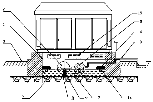
[0015] The invention provides a drainage system applied to a cable well, which can realize automatic drainage. The technical solutions of the present invention will be described in detail below with reference to the accompanying drawings to make it easier to understand and grasp.

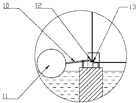
[0016] like figure 1 As shown, for the drainage system applied to the cable well, the bottom surface 2 of the cable well 1 is lower than the ground 3, the plane of the cable 4 in the cable well 1 is higher than the bottom surface 2, and the drainage system includes a The submersible pump 5 that discharges the accumulated water in the cable well 1 and a driving part 6 that drives the submersible pump 5 to work by monitoring the water level of the accumulated water. For drainage work, the specific water level must be lower than the cable potential, which can be set. The submersible pump 5 has a water inlet pipe 7 axially close to the bottom surface and a drainage pipe 8 that leads the accumulated wat...


PUM


Abstract

The invention discloses a drainage system applied to an electric cable well. The bottom surface of the electric cable well is lower than the ground, a plane in which an electric cable in the electric cable well is positioned is higher than the bottom surface, the drainage system comprises a submerged pump arranged in the electric cable well and used for discharging ponding water in the electric cable well, and a driving part for driving the submerged pump to work by monitoring the water level of the ponding water, the submerged pump is provided with a water inlet pipe axially adhered to the bottom surface and a drain pipe used for leading the ponding water out of the electric cable well, and the water level of the ponding water is lower than the plane in which the cable well is positioned. The drainage system provided by the invention adopts the driving part to monitor the water level of the ponding water so as to drive the submerged pump to drain away water, unmanned and automatic water drainage is achieved, manual duty water drainage is not required, and a floating ball structure has a simple structure, and is low in cost and strong in applicability.

Description

technical field [0001] The invention relates to a drainage system, in particular to a drainage system applied to a cable well. Background technique [0002] Cables are often laid in low-lying areas, and the cable position is below the ground. When external rainfall occurs, water seepage often occurs, causing the water level to be higher than the cable laying position. When the water level is higher than the cable, the cable will be immersed in water, which will reduce the insulation performance of the cable sheath, affect the work of the electrical circuit, and cause the equipment and facilities of the steel structure to rust and corrode, and even lead to circuit paralysis and endanger personal safety . In the prior art, the cable wells are generally laid in the dark, and the cable trenches are located below the ground, so natural drainage cannot be realized, and artificial drainage is used, which requires a large amount of labor and a high cost. SUMMARY OF THE INVENTION ...

Claims


Application Information

Patent Timeline
Patent Type & Authority Applications(China)
IPC IPC(8): E03F5/22
Inventor 尹立胜
Owner ZHEJIANG JINGGONG ENERGY TECH GRP CO LTD
Why Eureka
Try Eureka