Supercharge Your Innovation With Domain-Expert AI Agents!

Hydraulic slip

A slip and hydraulic technology, applied in the direction of drilling equipment, earthwork drilling, drill pipe, etc., can solve the problem of high casing damage, etc., achieve the effect of fast and simple unlocking, and prevent downward movement

Inactive Publication Date: 2016-03-02
TIANJIN HUIZHU PETROLEUM EQUIP SCI & TECH CO LTD
View PDF0 Cites 0 Cited by
  • Summary
  • Abstract
  • Description
  • Claims
  • Application Information

AI Technical Summary

Problems solved by technology

[0002] In field application, in order to prevent the pipe string from moving downward, the slip support method is generally adopted. At present, there are two most commonly used slips in the field: mechanical slips and hydraulic slips. Said that it is less affected by well conditions and easy to operate. Therefore, the application of hydraulic slips is increasing. However, hydraulic slips also have the defect that they are much more harmful to casing than mechanical slips. The main The reason is: the rolling force in the tubing always acts on the slips, and for high-pressure wells, the hydraulic pressure is extremely high

Method used


Image

  • Hydraulic slip
  • Hydraulic slip

Examples


Embodiment Construction

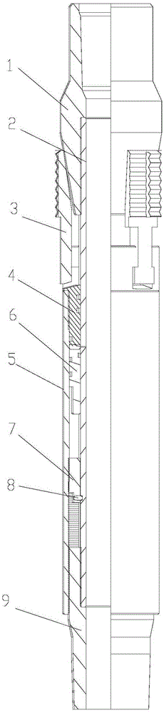
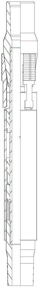
[0009] The specific implementation manner of the present invention will be described in detail below in conjunction with the accompanying drawings and preferred embodiments. Such as figure 1 and figure 2 As shown, a hydraulic slip includes an upper joint 1, a center pipe 2, a slip 3, a slip seat 4, a liquid cylinder 5, a piston 6, a reverse gear ring 7, a pin 8 and a lower joint 9, and the upper joint Threaded connection with the upper part of the central pipe, the slips are installed on the slip seat, the slips are matched with the inclined surface on the upper joint, and the slip seat is sleeved on the central pipe , the bottom of the slip seat is connected to the piston, the outside of the slip seat is connected to the upper part of the hydraulic cylinder, the lower part of the hydraulic cylinder is matched with the inverted gear ring, and the inverted gear ring is connected by a pin Installed on the central pipe, the lower joint is threadedly connected with the lower pa...


PUM


Abstract

The invention relates to the technical field of oil field and oil well drilling and exploiting, in particular to a hydraulic slip. The hydraulic slip comprises an upper connector, a central tube, a slip body, a slip base, a hydraulic cylinder, a piston, a reverse tooth ring, a pin and a lower connector. The upper connector is in threaded connection with the upper portion of the central tube. The slip body is installed on the slip base and matched with a slope on the upper connector. The central tube is sleeved with the slip base, the bottom of the slip base is connected with the piston, and the outer portion of the slip base is connected with the upper portion of the hydraulic cylinder. The lower portion of the hydraulic cylinder is matched with the reverse tooth ring, the reverse tooth ring is installed on the central tube through the pin, and the lower connector is in threaded connection with the lower portion of the central tube. The hydraulic slip has the self-locking function; as a slant tooth matched with the reverse tooth ring is arranged at the lower portion of the hydraulic cylinder, locking can be carried out in the process of opening the slip, and downward moving is prevented; after work is completed, the upper connector is lifted upwards, the pin is cut to be short, the slip is reset, and unlocking is fast and simple.

Description

technical field [0001] The invention relates to the technical field of oil well drilling and production in oil fields, in particular to a hydraulic slip. Background technique [0002] In field application, in order to prevent the pipe string from moving downward, the slip support method is generally adopted. At present, there are two most commonly used slips in the field: mechanical slips and hydraulic slips. It is said that it is less affected by well conditions and easy to operate. Therefore, the application of hydraulic slips is increasing. However, hydraulic slips also have the defect that they are much more harmful to the casing than mechanical slips. The main Reason is: the rolling force in the tubing acts on the slips all the time, and for high-pressure wells, the hydraulic pressure is extremely high. At this time, the force that the hydraulic slips act on the casing is the hydraulic pressure plus the support force, which is much more harmful to the casing than the m...

Claims


Application Information

Patent Timeline
IPC IPC(8): E21B19/10
CPCE21B19/10
Inventor 阚红砖阚正玉
Owner TIANJIN HUIZHU PETROLEUM EQUIP SCI & TECH CO LTD
Features
  • R&D
  • Intellectual Property
  • Life Sciences
  • Materials
  • Tech Scout
  • Unparalleled Data Quality
  • Higher Quality Content
  • 60% Fewer Hallucinations
Learn More