
Screw pump

A screw pump and stator technology, used in pumps, pump control, rotary piston pumps, etc., can solve problems such as preload mismatch, reduced service life, and low life of screw pump rotors and stators. The effect of improving the service life and improving the balance

Active Publication Date: 2016-03-02
ZOOMLION HEAVY IND CO LTD
View PDF5 Cites 2 Cited by
  • Summary
  • Abstract
  • Description
  • Claims
  • Application Information

AI Technical Summary

Problems solved by technology

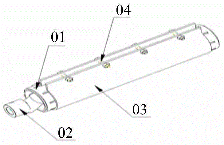
[0004] In the prior art, the clamp 03 for adjusting the pre-tightening force of the screw pair is an integral structure, but to ensure the normal service life of the screw pair, the adjustment of the pre-tightening force of the screw pair must be based on the minimum pre-tightening force between the screw pairs Adjustment, the pretightening force at the inlet end of the screw pair is the smallest, but according to the pressure relationship between the sealed cavity during operation, the pretightening force between the rotor 02 and the stator 01 in the screw pair gradually increases from the inlet end to the outlet end, From the inlet end to the outlet end, the friction between the stator 01 and the rotor 02 also gradually increases, which will inevitably cause the first damage of the rotor 02 and the stator 01 at the outlet end, reducing the service life
Furthermore, due to the influence of processing errors such as pitch, eccentricity, and radial dimensions of the stator 01 and rotor 02, the preload mismatch between the assembled rotor 02 and stator 01 will also be caused, which will intensify the contact between the cavities Partial wear, further reducing service life
[0005] Therefore, the service life of the screw pump rotor and stator adopted in the prior art is low

Method used


Image

  • Screw pump
  • Screw pump
  • Screw pump

Examples


Embodiment approach

[0048] Mode 1, each clamping hoop can be a hoop.

[0049] On the basis of the above method 1, if Figure 6 and Figure 7As shown, each hoop is hinged on the same shaft 6 , and the axis line of the shaft 6 is parallel to the axis line of the stator 2 .

[0050] Such as Figure 6 and Figure 7 As shown, a plurality of hoops are arranged in the axial direction of the screw pair, and each hoop is jointly hinged on the same shaft 6, and each hoop hinged on the shaft 6 is wrapped tightly and neatly on the outside of the stator 2, but each hoop Each hoop can adjust the force of the hoop on the corresponding stator 2 by adjusting the bolts on it, so as to realize the adjustment of the pre-tightening force between the part of the stator 2 and the hoop corresponding to the rotor 1 .

[0051] Such as Figure 8 ~ Figure 9 As shown, each clamp can be a double-bolt clamp 5, and the double-bolt clamp 5 is composed of two half-closed clamps.

[0052] Please refer to figure 2 , combin...


PUM


Abstract

The present invention relates to the technical field of engineering machinery, and discloses a screw pump, which comprises a rotor and a stator, wherein the stator is wrapped on the outer side of the rotor, the stator and the rotor form a screw pair, the inner wall of the stator and the outer wall of the rotor are connected in a sealed manner, a plurality of sealed cavities are formed between the inner side of the stator and the outer side of the rotor, the screw pump further comprises a pre-tightening force adjustment device, the pre-tightening force adjustment device comprises a plurality of clamping mechanisms wrapped on the outer side of the stator and aligned along the axial center line direction of the stator, and each clamping mechanism can be separately adjusted, ie., the action forces of each clamping mechanism on the stator can be controlled separately. With the technical scheme of the present invention, the action forces of each clamping mechanism on the stator can be adjusted so as to improve the pre-tightening force equilibrium between the stator and the rotor in the screw pair of the screw pump, such that the wear is generated between the stator and the rotor so as to prolong the service lives of the rotor and the stator.

Description

technical field [0001] The invention relates to the technical field of engineering machinery, in particular to a screw pump. Background technique [0002] At present, the screw pump is widely used as a conveying mechanism in infrastructure construction such as transportation, energy, and construction. It plays a very important role in improving construction efficiency and ensuring project quality. [0003] In the existing technology, such as figure 1 As shown, the screw pump includes a stator 01, a rotor 02, a clamp 03 wrapped outside the stator 01, and an adjusting bolt 04 on the clamp. The stator 01 and the rotor 02 form a screw pair, and the stator 01 and the rotor 02 in the screw pair form a With multiple sealed cavities, the pre-tightening force between all the contact surfaces of the stator 01 and the rotor 02 is the same after assembly. When the screw pair works normally, each sealed cavity generates working pressure, and the pressure difference between each sealed ...

Claims


Application Information

Patent Timeline
IPC IPC(8): F04C2/107F04C14/00
Inventor 尹友中裴杰周小宾冯怀
Owner ZOOMLION HEAVY IND CO LTD
Learn More