Supercharge Your Innovation With Domain-Expert AI Agents!

Multi-joint synchronous rotary axle structure

A rotating shaft structure and side shaft technology, applied in the field of multi-section rotating shaft structure, can solve the problems of large number of components, difficult to control the tightness, easy leakage of lubricating grease, etc.

Active Publication Date: 2016-03-02
FIRST DOME
View PDF8 Cites 0 Cited by
  • Summary
  • Abstract
  • Description
  • Claims
  • Application Information

AI Technical Summary

Problems solved by technology

[0007] However, due to the above-mentioned multi-section synchronous opening and closing shaft structure, it is necessary to combine multiple toothed pieces in order to obtain good transmission and the torque required to support the rotation angle, resulting in too many other components and poor production quality. It is not easy to control the disadvantage of uniformity; and it is difficult to control the tightness between the combined pieces, resulting in the leakage of lubricating grease; obviously, there are still many areas to be improved in terms of implementation

Method used


Image

  • Multi-joint synchronous rotary axle structure
  • Multi-joint synchronous rotary axle structure
  • Multi-joint synchronous rotary axle structure

Examples


Embodiment Construction

[0059] The present invention will be further described in detail below in conjunction with the accompanying drawings and specific embodiments.

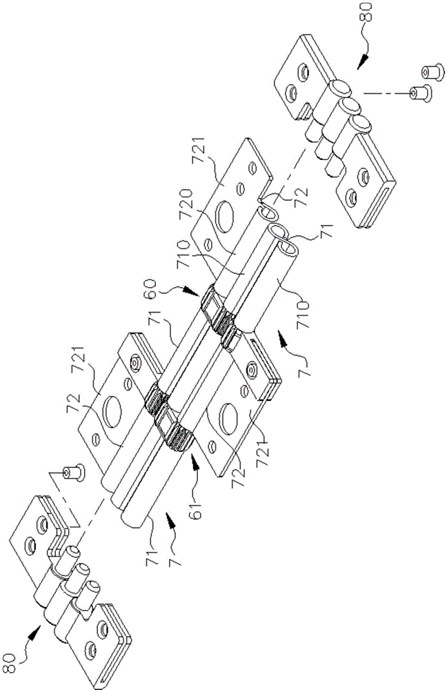
[0060] Please refer to Figure 3 to Figure 5 , the present invention includes a central axis 40 and two side shafts arranged in parallel on both sides of the central axis 40, which include a first side shaft 50 and a second side shaft 51, corresponding to the central shaft 40 and the two side shafts 50, 51 At a first position 400, 500, 510 and a second position 401, 501, 511 of the center shaft 40 and the two side shafts 50, 51, respectively, a first synchronous drive group 60 and a second synchronous Two synchronous actuation groups such as the actuation group 61, the two synchronous actuation groups 60, 61 are combined in opposite directions with respect to the joint between the central shaft 40, the first side shaft 50 and the second side shaft 51; as shown in the accompanying drawings , the first synchronous actuator group 60 is co...


PUM


Abstract

A multi-joint synchronous rotary axle structure includes a middle shaft and two parallel side shafts at two sides of the middle shaft. A first synchronous actuating assembly and a second synchronous actuating assembly are provided at two opposite positions of the middle shaft and the side shafts, which are connected in a reverse link relationship. The two side shafts can be rotated about the middle shaft to generate a synchronous reverse turning. A two-way shaft plate is provided between the middle shaft and each of the side shafts to provide the torsion of tuning so as to form a compact multi-joint synchronous rotary axle structure.

Description

technical field [0001] The invention relates to a multi-section rotating shaft structure, especially a rotating shaft structure that can be combined with two opposite folding and unfolding devices for synchronous rotating and unfolding operation. It has the advantage of being simpler and more feasible than the traditional one. Background technique [0002] Taking the electronic equipment that has been widely used nowadays as an example, it is usually composed of a base as a system end and a closing part as a display. The base and the closing part are connected by a pivot. And make the upper joint part can lift upwards with the pivot as the action axis to the use state, or reverse the upper joint part to be closed on the upper surface of the base to become the closed state. The importance of this type of pivot lies in that besides being the axis of action of the electronic device itself, the structural design must take into account the opening of the upper part to reach the o...

Claims


Application Information

Patent Timeline
Patent Type & Authority Applications(China)
IPC IPC(8): F16C11/04
CPCG06F1/1681
Inventor 徐安赐
Owner FIRST DOME
Features
  • R&D
  • Intellectual Property
  • Life Sciences
  • Materials
  • Tech Scout
  • Unparalleled Data Quality
  • Higher Quality Content
  • 60% Fewer Hallucinations
Learn More