Cylindrical test specimen lateral dynamic uniform distribution load testing apparatus

A test device and uniform loading technology, which is used in measurement devices, instruments, scientific instruments, etc., can solve the problems of inability to apply loads to structural specimens, harsh test conditions, and high danger, and achieve flexible and diverse loading methods and save testing. The effect of space and high test accuracy

Inactive Publication Date: 2016-03-02
PLA UNIV OF SCI & TECH
View PDF8 Cites 9 Cited by
  • Summary
  • Abstract
  • Description
  • Claims
  • Application Information

AI Technical Summary

Problems solved by technology

The cost of mold blaster and blast pit test is high, the risk is high, the test conditions are harsh, the required explosives are not easy to obtain, and the load duration is longer than the actual situation
The test of SHPB and light gas cannon can only be aimed at the material, and the load cannot be applied to the structural specimen
[0004] Although the drop hammer is close to explosion in the load action time and magnitude, it cannot achieve uniform loading and is mainly used for pseudo-static loading of structural specimens
There are few studies on impact dynamic load, and its applicable conditions and key influencing factors still need to be further studied. For axially stressed specimens such as structural columns or restrained beams, the current experimental equipment cannot achieve uniform distribution in the lateral direction. Dynamic response performance test under the joint action of load and axial force

Method used


Image

  • Cylindrical test specimen lateral dynamic uniform distribution load testing apparatus
  • Cylindrical test specimen lateral dynamic uniform distribution load testing apparatus
  • Cylindrical test specimen lateral dynamic uniform distribution load testing apparatus

Examples


Embodiment Construction

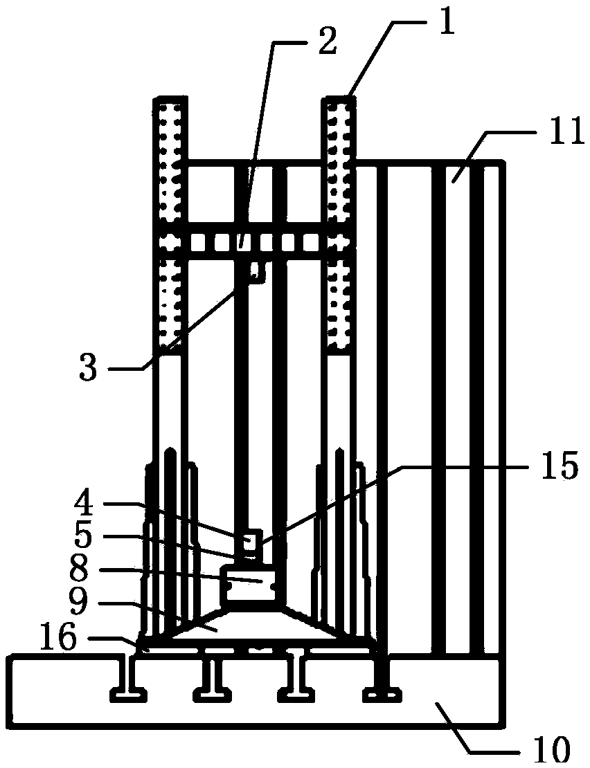
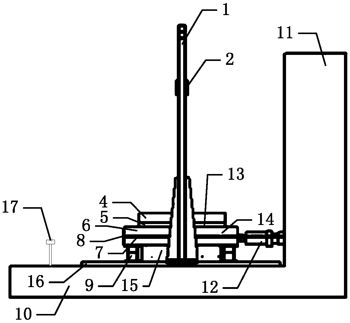
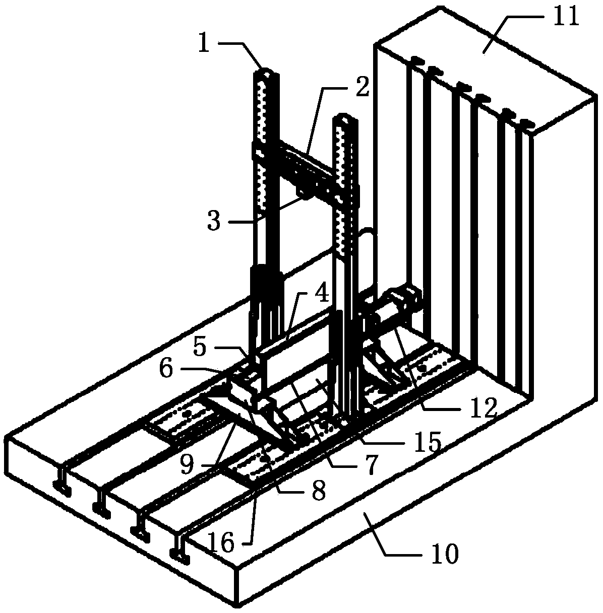
[0015] Such as Figure 1-3 As shown, the horizontal dynamic uniform loading test device of the columnar test piece of the present invention includes a reaction wall 11 located at one end of the columnar test piece 1, two supports 9 placed below the test piece 1 and close to the two ends of the test piece 1, The steel baffle 8 close to the other end of the test piece 1 also includes an anchor rod 7 and a horizontal actuator 12, one end of the anchor rod 7 is vertically connected to the steel baffle 8, and the other end is fixed on the reaction force In the vertical channel of the wall 11, the horizontal actuator 12 is placed between the reaction wall 11 and the test piece 1, one end of which is fixed on the reaction wall 11, and the other end withstands the test piece 6 and is close to the reaction force. one end of wall 11,

[0016] It also includes a door-type guide rail 1 perpendicular to the plane of the foundation 10, and a load-bearing beam 2 that can slide freely along ...


PUM


Abstract

The invention discloses a cylindrical test specimen lateral dynamic uniform distribution load testing apparatus. The apparatus comprises a reaction wall (11), holders (9), a steel baffle (8), an anchor arm (7) and a horizontal actuator (12). One end of the horizontal actuator (12) is fixed at the reaction wall (11), and the other end of the horizontal actuator (12) abuts against one end of a test specimen (6) close to the reaction wall (11). The apparatus further comprises a door-type guide rail (1) perpendicular to a foundation plane (10), a weight-bearing beam (2) capable of falling free along the door-type guide rail (1), a drop hammer (3) fixedly connected to lower middle part of the weight-bearing beam (2), a water bag (5) on the upper portion of the test specimen (1), and a steel distribution beam (4) above the water bag (5). The apparatus is capable of testing the dynamic response characteristics of beams, columns and other cylindrical test specimens under interaction of transverse uniform dynamic load and axial force.

Description

technical field [0001] The invention belongs to the technical field of mechanical testing of building structures, in particular to a testing device capable of testing the dynamic mechanical properties of axially stressed columnar specimens such as beams and columns under the action of transverse impact uniformly distributed dynamic loads. Background technique [0002] At present, occasional explosion disasters such as gas explosions and terrorist attacks occur frequently, often causing damage to engineering structures and even collapses. Therefore, the dynamic response of columnar specimens, such as beams, columns and other structural specimens under blast loads, has always been a research hotspot in the academic circles. In the range of common proportional explosion distances, it is generally considered that the explosion load on the specimen is a uniformly distributed dynamic load. Due to the difficulty and high cost of field explosion tests, people have been working hard ...

Claims


Application Information

Patent Timeline
Patent Type & Authority Applications(China)
IPC IPC(8): G01N3/00
Inventor 陈力方秦潘腾张亚栋相恒波柳锦春
Owner PLA UNIV OF SCI & TECH
Why Eureka
Try Eureka