
Static pressure supporting hydraulic cylinder structure and lateral load resistance testing method thereof

A technology of static pressure support and side load, which is applied in the testing of machine/structural components, fluid pressure actuation system testing, and testing of material strength by applying repetitive force/pulsation force, etc. It can solve the problems affecting the control accuracy and stability of hydraulic cylinders Sexuality, uneven artificial loading force, increased frictional resistance of the piston rod, etc., to achieve the effect of flexible loading mode, less manual intervention factors, and reduced frictional resistance

Pending Publication Date: 2021-06-04
天津福云天翼科技有限公司
View PDF0 Cites 0 Cited by
  • Summary
  • Abstract
  • Description
  • Claims
  • Application Information

AI Technical Summary

Problems solved by technology

[0005] In view of this, the present invention aims to propose a hydrostatically supported hydraulic cylinder structure to solve the problems existing in the prior art. The direction of the loading force applied to the hydraulic cylinder by the guide belt is fixed, and the force of manual loading is uneven, which increases the number of pistons. The friction resistance when the rod moves, and when the piston rod bears a certain eccentric load, the sealing performance of the seal is reduced, which affects the control accuracy and stability of the hydraulic cylinder.
[0006] The present invention also proposes a method for testing the lateral load resistance of the hydrostatically supported hydraulic cylinder structure, in order to solve the technical problem existing in the prior art that the loading method adopts many manual intervention factors, resulting in inaccurate measured loading data

Method used


Image

  • Static pressure supporting hydraulic cylinder structure and lateral load resistance testing method thereof
  • Static pressure supporting hydraulic cylinder structure and lateral load resistance testing method thereof

Examples


Embodiment Construction

[0037] It should be noted that the features in the present invention in the present invention can be combined with each other in the case of an unable conflict.

[0038] In the description of the present invention, it is to be understood that the terms "center", "longitudinal", "horizontal", "upper", "lower", "front", "post", "left", "right", " The orientation of the orientation of the orientation of the direction "," horizontal "," top "," bottom "," inside "," outside ", etc. is based on the orientation or positional relationship shown in the drawings, is only for convenience of describing the present invention and Simplify the description, rather than indicating or implying that the device or element must have a specific orientation, constructed and operated in a particular direction, and thus is not to be construed as limiting the invention. Moreover, the terms "first", "second", etc. are only used to describe purposes, and cannot be understood as an indication or implies rela...


PUM


Abstract

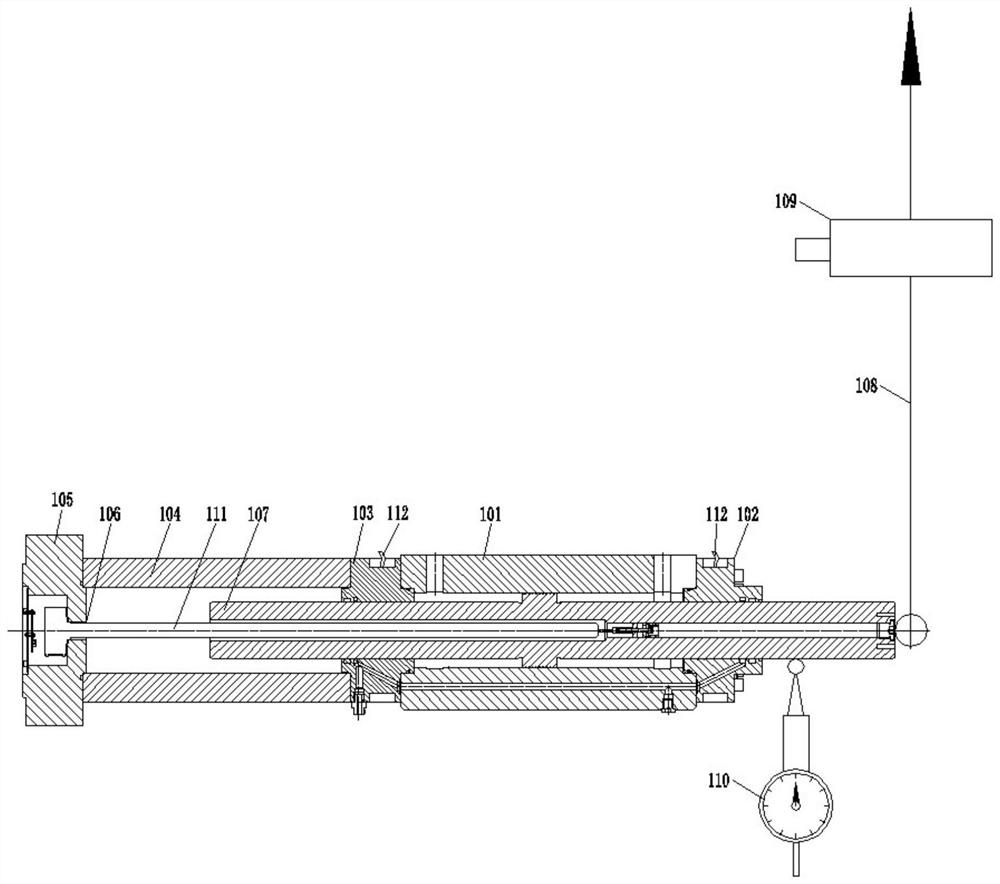
The invention provides a static pressure supporting hydraulic cylinder structure. The static pressure supporting hydraulic cylinder structure comprises a cylinder barrel, a front bearing, a rear bearing, a tail barrel, a rear flange, a displacement sensor, a piston, a flexible sling, a pressure sensor and a dial indicator, wherein the front bearing is connected with the front end of the cylinder barrel; the rear bearing is connected with the rear end of the cylinder barrel; the front end of the tail barrel is connected with the rear bearing, the rear end of the tail cylinder is connected with the rear flange, and the displacement sensor is connected into the rear flange; a piston rod at the inner side end of the piston penetrates through the tail barrel to be connected with the displacement sensor; the outer side end of the piston is connected with the lower end of the flexible sling, the pressure sensor is connected to the flexible sling, the upper end of the flexible sling is connected with a loading device, and the dial indicator is connected with the outer side end of the piston. The static pressure supporting hydraulic cylinder structure has the advantages that the outer side of the piston rod is connected with the flexible sling, external loading force is tested through the pressure sensor, and when a hydraulic cylinder is used, the whole hydraulic cylinder has the advantages of being small in friction force, high in bearing capacity, long in service life and the like.

Description

Technical field [0001] The present invention belongs to the technical field of static pressing hydraulic cylinders, and more particularly to a static pressure support hydraulic cylinder structure and its anti-side direction load test method. Background technique [0002] The hydraulic cylinder is used as a power component and an actuator that requires low friction, good anti-side load capacity, and high speed motion. Conventional hydraulic cylinders typically employ the guide belt as a guide and lateral load bearing member to measure the capacity of the anti-side load of the hydraulic cylinder. [0003] However, since the guide belt is not fixed in the direction of the loaded capacity applied to the hydraulic cylinder, the load tool is used, the loading device is more, and the loading capacity is applied. When the load capacity is uneven, the actual operation is not only added to the piston rod The frictional resistance, and when the piston rod is subjected to a certain bias supp...

Claims


Application Information

Patent Timeline
Patent Type & Authority Applications(China)
IPC IPC(8): F15B15/14F15B19/00G01N3/36G01B5/02G01M99/00
CPCF15B15/14F15B19/00G01B5/02G01M99/007G01N3/36
Inventor 高朋
Owner 天津福云天翼科技有限公司
Learn More