Leveraged input device micro switch key

A technology of input devices and micro switches, applied in the direction of electric switches, tactile feedback, electrical components, etc., can solve problems such as contact aging and misoperation

Active Publication Date: 2016-03-02
DONG GUAN LONGIDEAL IND CO LTD
View PDF5 Cites 5 Cited by
  • Summary
  • Abstract
  • Description
  • Claims
  • Application Information

AI Technical Summary

Problems solved by technology

In addition, the contacts of the light ...

Method used


Image

  • Leveraged input device micro switch key
  • Leveraged input device micro switch key
  • Leveraged input device micro switch key

Examples


Embodiment 1

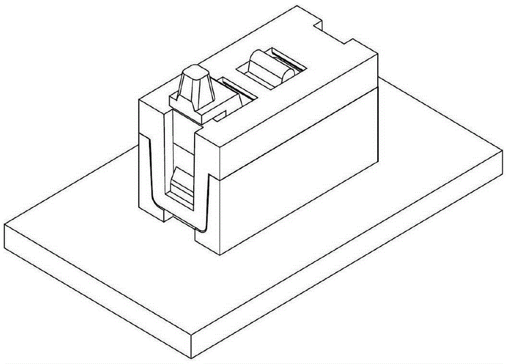
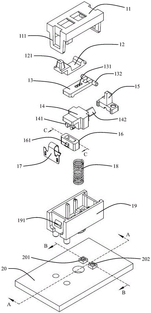
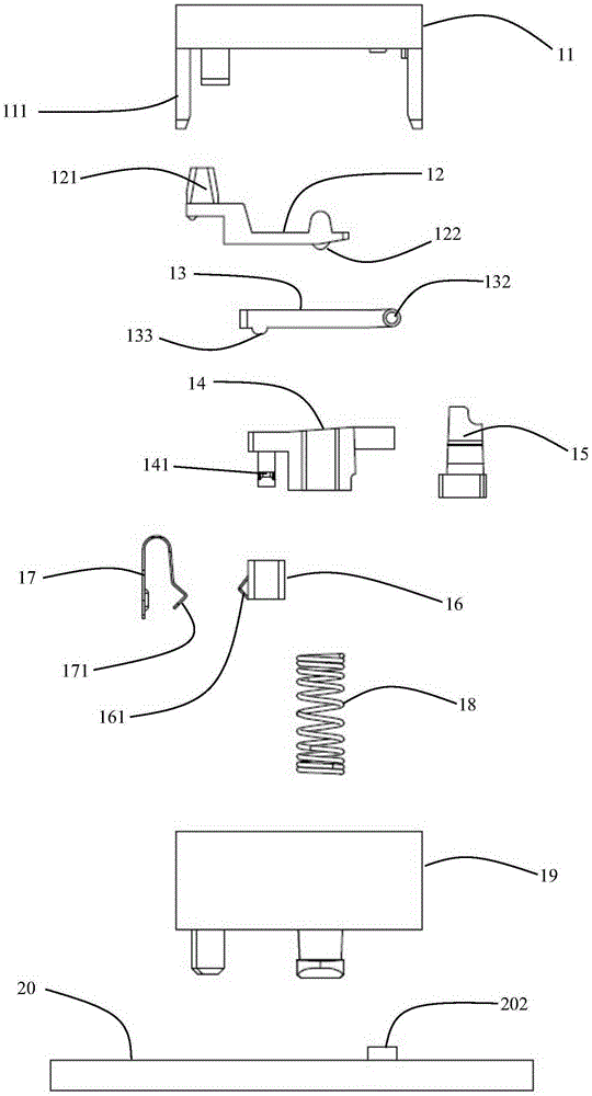
[0090] The isometric side view of a specific embodiment of a lever-type input device micro-switch button involved in the first embodiment is as follows: figure 1 As shown, the isometric exploded structure diagram is shown in figure 2 As shown, the exploded structure diagram of the front view side is shown in image 3 shown. It adopts a sliding lever structure with adjustable pressing force and a photoelectric switch functional structure in the form of an optical path.

[0091] It consists of an upper fixed shell 11, a sliding lever trigger mechanism (including the first lever 12 and the trimmer 13), the first pressing block 14, the first optical assembly 15, the movable slider 16, the metal dome 17, the spring 18, the lower fixed Shell 19, PCB printed circuit board 20, SMDIR tube (surface mount infrared light emitting diode) 201, SMDPT tube (surface mount photoelectric receiving tube) 202 is composed.

[0092] The upper fixed shell 11 has buckle lock rings 111 under both s...

Embodiment 2

[0108] A lever-type input device micro-switch key involved in the second embodiment adopts a fixed lever structure with a fixed single pressing force and a photoelectric switch functional structure in the form of an optical path.

[0109] The fixed lever structure does not need to be adjusted, but only uses a single fixed pressing force to combine the first lever 12 and the fine-tuning piece 13 in the first embodiment into one part—the second lever 22 . In the second embodiment, the first lever 12 and the fine-tuning sheet 13 in the first embodiment are combined into a single part---the second lever 22 . All other structures are identical with Embodiment 1, and its isometric side exploded structure diagram is as Figure 8 shown.

[0110] It consists of an upper fixed shell 11, a second lever 22, a first pressing block 14, a first optical assembly 15, a movable slider 16, a metal shrapnel 17, a spring 18, a lower fixed shell 19, a PCB printed circuit board 20, an SMDIR tube ( S...

Embodiment 3

[0113] A lever-type input device micro-switch key involved in the third embodiment, when the key is released and in a static state, the light path is in a disconnected state along the figure 2 The cross-sectional view in the B-B direction is attached Figure 9 As shown, it adopts a sliding lever structure with adjustable pressure and a photoelectric switch functional structure in the form of an optical path.

[0114] It consists of an upper fixed shell 11, a sliding lever trigger mechanism (including the first lever 12 and fine-tuning sheet 13), the first pressing block 14, the second optical assembly 35, the movable slider 16, the metal dome 17, the spring 18, the lower fixed Shell 19, PCB printed circuit board 20, SMDIR tube (surface mount infrared light emitting diode) 201, SMDPT tube (surface mount photoelectric receiving tube) 202 is composed.

[0115] Its described second optical assembly 35 is composed of a combined prism formed by a Fresnel collimating / focusing lens ...


PUM


Abstract

The invention relates to a leveraged input device micro switch key which can be used in computer peripherals, electronic instruments and man-machine control systems. The leveraged input device micro switch key comprises a switch control body and a PCB (printed circuit board) which are split, and the switch control body can be replaced and chosen as needed. The switch control body comprises a leveraged touch structure, a switch function structure, and a pressing section falling structure. The leveraged touch structure is employed to achieve an amplified trigger stroke through a micro stroke so as to control the switch function structure, and the pressing section falling structure produces clear falling sound of the pressing section of the key. The leveraged touch structure is a sliding lever structure with adjustable pressing force or a fixed lever structure with single fixed pressing force. The switch function structure is a light path type photoelectric switch function structure or a metal contact point/elastic sheet contact type switch function structure.

Description

technical field [0001] The invention relates to an input device that can be used in computer peripheral equipment, electronic instruments, and man-machine control systems, and particularly relates to a lever-type micro switch button of the input device. Background technique [0002] Existing key switches for computer peripherals, electronic instruments, and input devices of man-machine control systems, such as mouse key switches, machine tool control switches, aerospace switches, military instrument switches, medical equipment switches, automation equipment controls In the field of switches and other fields, its structure is basically a light touch switch. [0003] The light touch switch is also called a sensitive switch, that is, when it is used to meet the conditions of the operating force, the switch function is closed and turned on by applying pressure to the switch operation direction, and the switch is turned off when the pressure is removed. Its internal structure is ...

Claims


Application Information

Patent Timeline
IPC IPC(8): H01H13/14H01H13/20
CPCH01H13/14H01H13/20H01H2215/03H01H2227/034
Inventor 郎欢标
Owner DONG GUAN LONGIDEAL IND CO LTD
Why Eureka
Try Eureka