Portable 35KV fuse core replacing device and quick core replacing method

A fuse, portable technology, applied in the field of portable 35KV fuse core change device and quick core change, it can solve the problems of long time-consuming fuse change core, cumbersome operation, etc., to achieve simple and clear steps, simple operation and reliability strong effect

Active Publication Date: 2016-03-02
XINGAN POWER SUPPLY CO
View PDF10 Cites 2 Cited by
  • Summary
  • Abstract
  • Description
  • Claims
  • Application Information

AI Technical Summary

Problems solved by technology

[0007] The purpose of the present invention is to solve the problems of long time-consuming and cumbersome operation of the existing fuse core change, to provide a convenient 35KV fuse core change device, and also to provide a corresponding fast core change method

Method used


Image

  • Portable 35KV fuse core replacing device and quick core replacing method
  • Portable 35KV fuse core replacing device and quick core replacing method
  • Portable 35KV fuse core replacing device and quick core replacing method

Examples


Embodiment 1

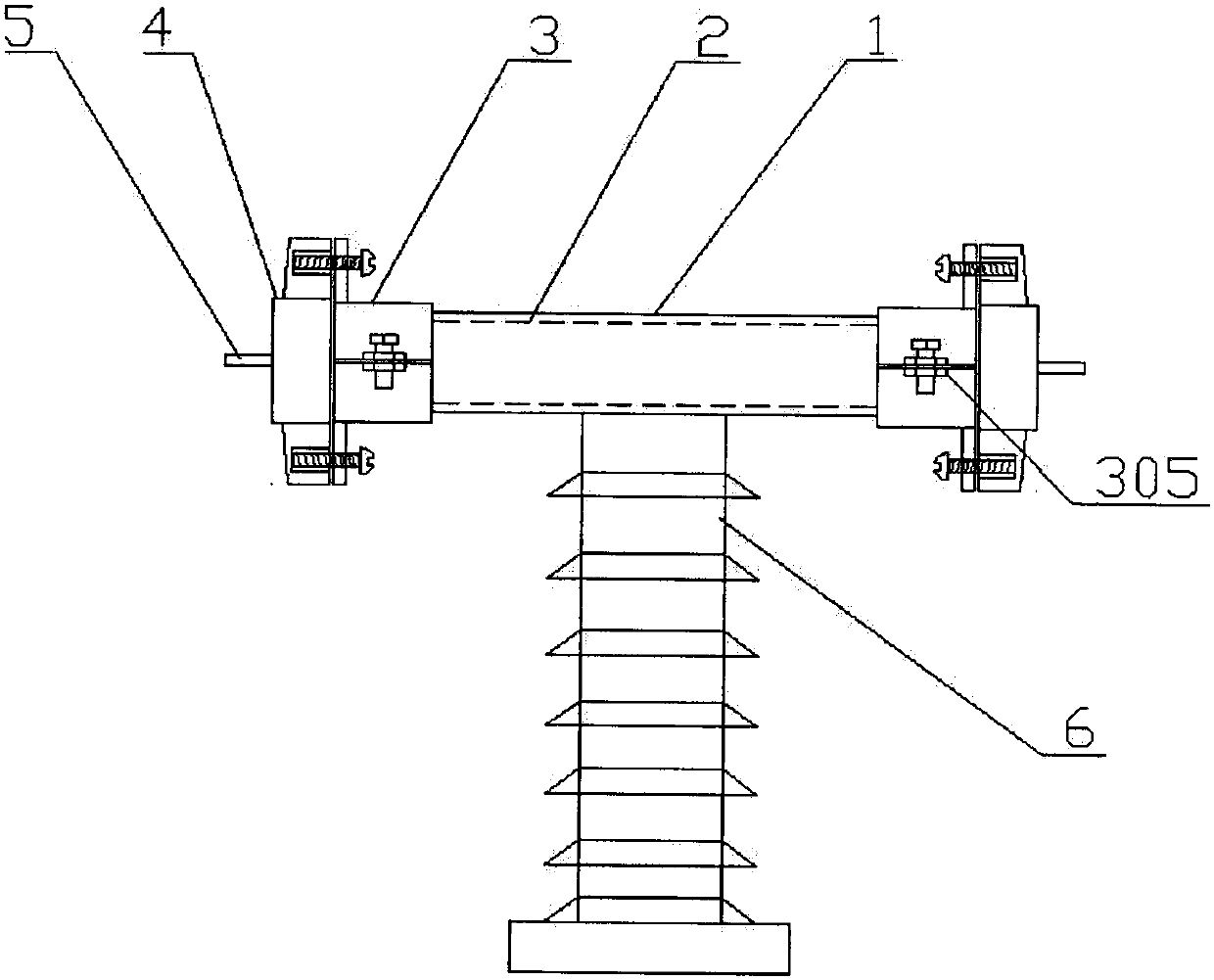
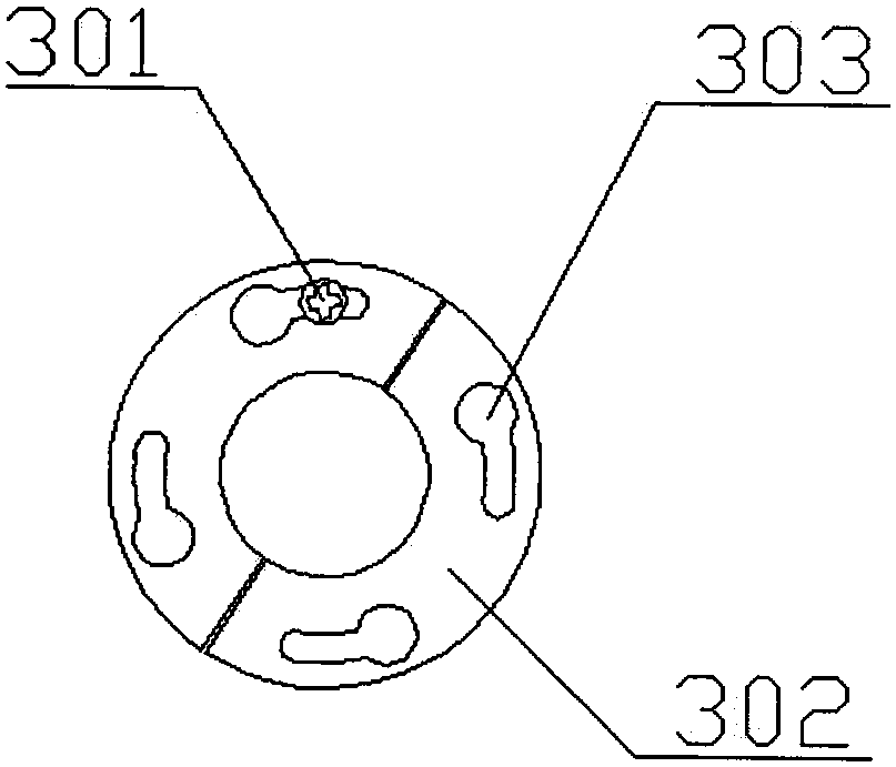
[0037] Embodiment 1: see figure 1 , figure 2 , a convenient 35KV fuse core replacement device, including a fuse sleeve 1, a fuse tube 2, a cover clamp 3, a terminal cover 4, and a terminal 5; the fuse sleeve 1 is fixed on a supporting insulator 6 Above, the terminal cover plate 4 is set at both ends of the fuse sleeve 1, and forms a closed area with it to enclose the fuse tube 2; the fuse tube 2 forms a circuit connection with the terminal 5; the fuse sleeve 1 and the terminal The cover plate 4 is connected through the cover plate clamper 3; the left end of the cover plate clamper 3 is fixedly connected with the fuse porcelain sleeve 1; Detachable connection, the terminal cover is provided with an engaging part corresponding to the track slot, the engaging part is located in the narrow area of ​​the track slot 303, the terminal cover is clamped, and the engaging part is located in the track slot 303 In the open area the terminal cover is loosened.

[0038] see figure 2 ,...

Embodiment 2

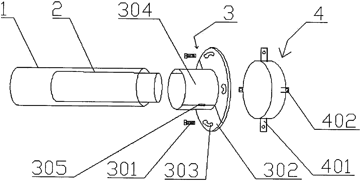
[0039] Example 2: see Figures 1 to 5 , the portable 35KV fuse core changing device of this embodiment is basically the same as that of Embodiment 1, the only difference is that the cover clamp is divided into two parts that are symmetrical up and down, and is arranged on the core changing sleeve 304 The sleeve connecting piece 305 is connected into one; the core changing sleeve 304 covers the end of the fuse sleeve, so that the fuse sleeve is fixedly connected with the cover clamp; the sleeve connecting piece can be adjusted by bolts. The gap distance between the upper and lower parts of the board clamp.

[0040] The sleeve connector 305 includes connecting pieces and bolts; the connecting pieces are symmetrically arranged on the edges of the upper and lower core changing sleeves, and the connecting pieces are provided with threaded holes, and the bolts are vertically screwed into the upper and lower threaded holes, so that the upper and lower , The lower connecting piece is...

Embodiment 3

[0041] Embodiment 3: see Figures 1 to 5 , the portable 35KV fuse core replacement device of this embodiment is basically the same as that of Embodiment 2, the only difference is that the size and shape of the terminal cover 4 matches the fuse sleeve 1, and the terminal cover is outward Extend the cover plate protrusion 401 corresponding to the track slot 303; the cover plate protrusion 401 is provided with a cover plate screw hole 402, and the cover plate fixing bolt 301 as the engaging part is screwed into the cover plate screw hole 402 Inside.

[0042] The terminal cover plate 4 is made of aluminum material, the core changing end plate 302, the core changing sleeve 304, the sleeve connector 305 and its bolts are made of stainless steel; the core changing end plate 302 and the core changing sleeve 304 are integrated Formed, the cover raised portion 401 is welded around the terminal cover 4 .

[0043] The specifications of the following parts are: terminal cover plate 4 is ...


PUM


Abstract

The invention discloses a portable 35KV fuse core replacing device. A fuse porcelain bushing is fixed on a support insulator. Wiring end cover plates are arranged at the two ends of the fuse porcelain bushing to form a closed area in which a fuse tube is wrapped. The fuse tube and wiring terminals form circuit connection. The fuse porcelain bushing and the wiring end cover plates are connected by cover plate clamping devices. The left ends of the cover plate clamping devices are fixedly connected with the fuse porcelain bushing, and the right ends of the cover plate clamping devices are detachably connected with the wiring end cover plates through track clamping slots. The wiring end cover plates are provided with clamping parts corresponding to the track clamping slots. When the clamping parts are in the narrow areas of the track clamping slots, the wiring end cover plates are clamped; and when the clamping parts are in the wide areas of the track clamping slots, the wiring end cover plates are released. The corresponding core replacing method of the invention comprises the steps of unscrewing connectors, removing the wiring end cover plates, replacing the fuse tube, closing the wiring end cover plates, tightening the connectors, and the like. The device and the method of the invention have the characteristics of short core replacing time and simple operation.

Description

technical field [0001] The invention relates to the technical field of overload and short-circuit protection for electrical equipment such as high-voltage transmission lines, voltage transformers, and voltage transformers, and in particular to a portable 35KV fuse core replacement device. Background technique [0002] The 35kV high-voltage current-limiting fuse is suitable for AC 50HZ, rated voltage 35KV systems, mainly used in 35kV systems for rural and urban power grids, and can also be used in conjunction with other electrical appliances (such as switches, contactors, etc.) as motors, transformers, Overload or short circuit protection of electrical equipment such as capacitors; it can also be used in other similar places. [0003] At present, 35kV fuses are composed of melt tubes, porcelain sleeves, fastening flanges, rod-shaped post insulators and terminal caps. Fix the terminal caps and fuse tubes at both ends in the porcelain bushing by pressing, and then fix the porc...

Claims


Application Information

Patent Timeline
Patent Type & Authority Applications(China)
IPC IPC(8): H01H85/22
CPCH01H85/22
Inventor 乔军
Owner XINGAN POWER SUPPLY CO
Why Eureka
Try Eureka