Method and apparatus for separating adhesive tapes

A technology of peeling device and adhesive tape, which is applied in the direction of electrical components, semiconductor/solid-state device manufacturing, circuits, etc., and can solve the problems of inability to perform the peeling function and reduced adhesive force

Inactive Publication Date: 2016-03-02
NITTO DENKO CORP
View PDF5 Cites 11 Cited by
  • Summary
  • Abstract
  • Description
  • Claims
  • Application Information

AI Technical Summary

Problems solved by technology

Since the double-sided adhesive tape is softened by heating, when the release tape is pasted like the conventional protective tape, the release tape will soften, so the adhesive force will decrease and the release function will not be able to be performed.

Method used


Image

  • Method and apparatus for separating adhesive tapes
  • Method and apparatus for separating adhesive tapes
  • Method and apparatus for separating adhesive tapes

Examples


Embodiment Construction

[0046] Hereinafter, embodiments of the present invention will be described with reference to the drawings.

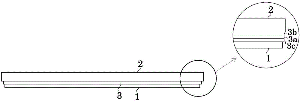
[0047] The adhesive tape peeling apparatus of this invention is provided in a support plate separation apparatus. That is, if figure 1 As shown, the adhesive tape peeling device is used to attach the support plate 2 made of stainless steel, glass substrate or silicon substrate concentrically to the support plate 2 via the double-sided adhesive tape 3 before back grinding. A device for separating a wafer 1 (hereinafter, appropriately referred to as “wafer 1 ”) from the support plate 2 . In addition, the support plate 2 has substantially the same shape as the wafer 1 , and its diameter is equal to or larger than the diameter of the wafer 1 .

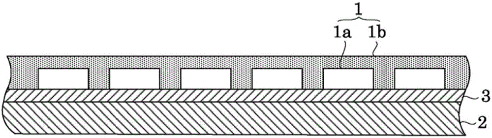
[0048] Here, wafer 1 is formed as follows. Bare chips 1 a obtained by performing a dicing process after forming circuits on the wafer surface are inspected, and only qualified bare chips 1 a are screened out. In such a manner t...


PUM


Abstract

The invention provides a method and apparatus for separating adhesive tapes. The adsorption surface of a peeling roller is used to adsorb a dual-surface adhesive tape on the periphery of a wafer. The peeling roller is rotated, at the same time, the peeling roller is abutted on the wafer, then the peeling roller and wafer are horizontally moved relative to the ground, the dual-surface adhesive tape is peeled off from the wafer, and a start end for peeling is formed. Then the rotation of the peeling roller is stopped. The peeling roller and a handling member are used to hold the start end for peeling, and the dual-surface adhesive tape is peeled off from the wafer. After the dual-surface adhesive tape is completely peeled off, the dual-surface adhesive tape is released from the handling member and is dumped into a belt recovering part.

Description

technical field [0001] The present invention relates to an adhesive tape peeling method and an adhesive tape peeling device for peeling an adhesive tape attached to a semiconductor wafer. Background technique [0002] When a semiconductor wafer (hereinafter, appropriately referred to as "wafer") becomes thinner by back grinding, a protective tape is attached to the surface of the wafer. After backside grinding, a peeling tape is attached to the protective tape, and the protective tape is peeled off from the wafer in such a manner that the protective tape and the peeling tape are integrated by peeling off the peeling tape (see Japanese Patent Application Laid-Open No. 2004-273527 Bulletin). [0003] In addition, in recent years, there has been a tendency to backgrind semiconductor wafers (hereinafter, appropriately referred to as “wafers”) to have a thickness of several tens of μm in response to demands for high-density packaging. Therefore, during the period from the back ...

Claims


Application Information

Patent Timeline
Patent Type & Authority Applications(China)
IPC IPC(8): H01L21/683
CPCH01L21/6836
Inventor 长谷幸敏山本雅之
Owner NITTO DENKO CORP
Why Eureka
Try Eureka