Cable paying-off machine

A pay-off and axis technology, which is applied in the direction of cable laying equipment, etc., can solve the problems of heavy workload, small space, damage to the outer skin, etc., and achieve the effects of improving speed and quality, saving labor costs, and prolonging the service life

Active Publication Date: 2016-03-02
STATE GRID CORP OF CHINA +2
View PDF6 Cites 0 Cited by
  • Summary
  • Abstract
  • Description
  • Claims
  • Application Information

AI Technical Summary

Problems solved by technology

In the process of electric power construction or electrical installation, it is usually necessary to lay a large number of cables in the dug trenches. Usually, the cables are packaged in rolls. When laying, the wires need to be released, and many corners must be passed through when laying. The traditional laying method is to invest at least one person in each corner for laying work, so the workload is heavy, and many construction personnel are invested, which is time-consuming and laborious
Moreover, some corners have narrow spaces, such as cable trenches, cable interlayers, cable shafts, etc. Even if personnel are invested, it is not easy to lay cables quickly.
During the laying process, the cable is easy to rub against the corner and damage the outer skin, which seriously affects the speed and quality of cable laying

Method used


Image

  • Cable paying-off machine
  • Cable paying-off machine
  • Cable paying-off machine

Examples


Embodiment Construction

[0019] Below in conjunction with accompanying drawing and specific embodiment the present invention is described in detail:

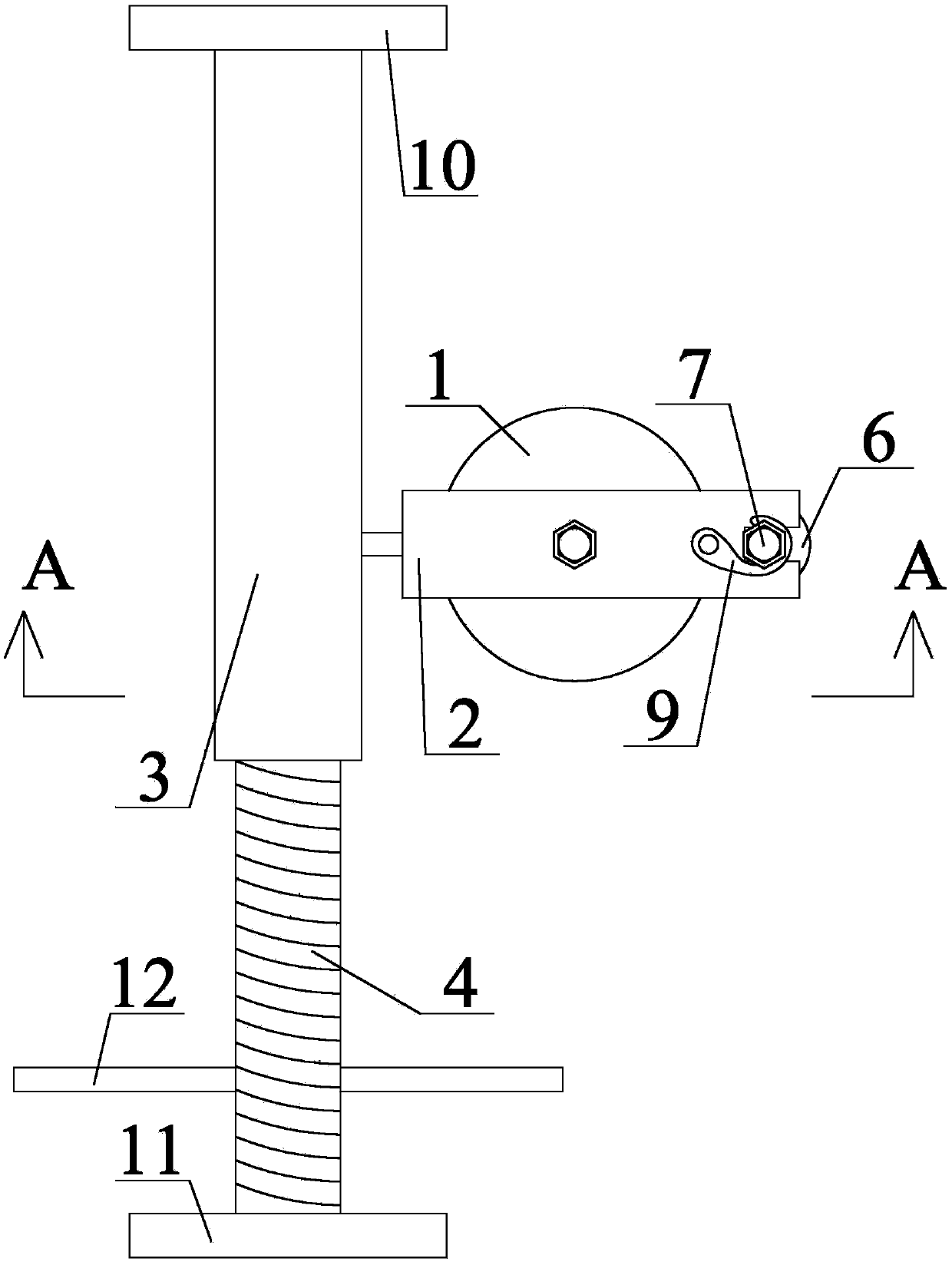
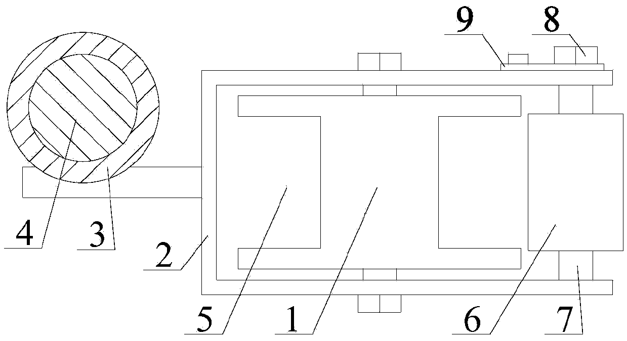
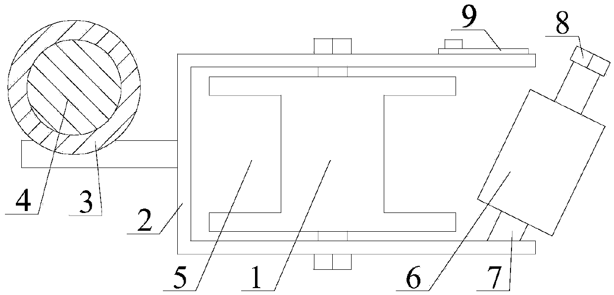
[0020] Specific examples, such as figure 1 , figure 2 and image 3 As shown, a pay-off device includes a length adjustment rod, a thread wheel 1 and a clip 2, the length adjustment rod is arranged horizontally, the length adjustment rod includes a fixed rod 3 and a telescopic rod 4, and the fixed rod 3 is set on the outside of the telescopic rod 4, The telescopic rod 4 is elongated or shortened in the fixed rod 3 and forms a locking fit with the fixed rod 3. The wire passing wheel 1 is arranged on one side of the fixed rod 3 and the axis of the wire passing wheel 1 is vertically arranged. The clip 2 is formed by the upper The clamping structure composed of the splint and the lower splint, one end of the clip 2 is an open end, the other end of the clip 2 is a closed end, the open end of the clip 2 is facing the side away from the fixed rod 3, and the ...


PUM


Abstract

A cable paying-off machine is disclosed, belonging to the technical field of electric power construction equipment. The cable paying-off machine comprises a length adjusting rod, a cable-across wheel and a clamp; the length adjusting rod is horizontally arranged; the length adjusting rod comprises a fixed rod and a telescopic rod; the fixed rod is arranged on the external of the telescopic rod in a sleeving manner; the telescopic rod is extended or shortened in the fixed rod, and locking fit is formed between the telescopic rod and the fixed rod; the cable-across wheel is arranged on one side of the fixed rod, and the shaft line of the cable-across wheel is vertically arranged; the clamp is in a clamping structure, and the clamp is composed of an upper clamping plate and a lower clamping plate; an opening end is arranged at one end of the clamp while a closed end is arranged at the other end of the clamp; the opening end of the clamp faces to one side far from the fixed rod; the cable-across wheel is positioned between the upper clamping plate and the lower clamping plate of the clamp, and running fit is formed between the cable-across wheel and the clamp; and the closed end of the clamp is fixedly connected with the fixed rod. Due to the cable paying-off machine, manpower and human cost are saved; the cable paying-off machine is time-saving and labor-saving; in addition, the condition that the outer skins of the cables are damaged caused by rubbing with corners is avoided; and the cable laying speed and quality are greatly improved, and the service life of the cables is prolonged.

Description

technical field [0001] The invention belongs to the technical field of electric power construction equipment, and relates to a wire pay-off device. Background technique [0002] With the rapid development of my country's electric power industry, the construction, expansion and renovation of substations are increasing. In the process of electric power construction or electrical installation, it is usually necessary to lay a large number of cables in the dug trenches. Usually, the cables are packaged in rolls. When laying, the wires need to be released, and many corners must be passed through when laying. The traditional laying method is to invest at least one person in each corner for laying work, so the workload is heavy, and many construction workers are invested, which is time-consuming and laborious. Moreover, some corners have narrow spaces, such as cable trenches, cable interlayers, cable shafts, etc. Even if personnel are invested, it is not easy to lay cables quickly...

Claims


Application Information

Patent Timeline
Patent Type & Authority Applications(China)
IPC IPC(8): H02G1/06
CPCH02G1/06
Inventor 周兆辉丛辉师威刘立强赵之洞周建军刘伟良袁继森安英娟檀志峰尹翠华张广平吕乐乐石赛亮师进冲
Owner STATE GRID CORP OF CHINA
Why Eureka
Try Eureka