
Press mounting base of motor rotor and press mounting method of press mounting base

A motor rotor, press-fit technology, applied in the manufacture of stator/rotor body, hand-held tools, manufacturing tools, etc., can solve the problems of inability to stack, press-fit, lack of benchmarks, etc., to reduce consumption and manufacturing processes, The effect of improving production efficiency and reducing costs

Inactive Publication Date: 2016-03-02
JIANGSU TONGDA POWER TECH
View PDF0 Cites 0 Cited by
  • Summary
  • Abstract
  • Description
  • Claims
  • Application Information

AI Technical Summary

Problems solved by technology

[0003] In actual production and manufacturing, generally speaking, some motor rotor products adopt the heat-shrink shaft technology. Now, in order to ensure the balance of the motor rotor, the positioning key and mark groove are canceled in the stamping manufacturing process, and the shaft hole and ventilation slot are used for positioning. , such a process ensures the dynamic balance requirements of the motor rotor, but also brings corresponding problems: press-fitting problem
Stator punches without positioning slots and marking slots lack benchmarks during the press-fitting process, and there is no way to effectively laminate them

Method used


Image

  • Press mounting base of motor rotor and press mounting method of press mounting base

Examples


Embodiment Construction

[0025] The present invention will now be described in further detail with reference to the drawings. These drawings are all simplified schematic diagrams, which merely illustrate the basic structure of the present invention in a schematic manner, so they only show the structures related to the present invention.

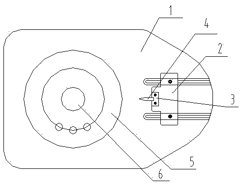
[0026] Such as figure 1 As shown, a press-fitting base of a motor rotor includes a work surface 1, a dummy shaft 6 for covering the rotor core 5, a base 2, a fixing plate 3, and a first slot marked for positioning the rotor core 5 The guide rib 4; the false shaft 6 is vertically arranged on the work surface 1, and is biased to one side of the longitudinal direction of the work surface 1, the base 2 is movably connected to the other side of the longitudinal direction of the work surface 1, and the base 2 faces the side of the false shaft 6 The guide rib 4 is fixed by the fixing plate 3, the guide rib 4 points to the dummy shaft 6, and the distance between the guide rib ...


PUM


Abstract

The invention discloses a press mounting base of a motor rotor and a press mounting method of the press mounting base. The press mounting base comprises a working table, a false shaft, a base, a fixed plate and a guide rib, wherein the false shaft is used for sleeving a rotor iron core, the guide rib is used for positioning a marked first groove of the rotor iron core, the false shaft is vertically arranged on the working table and is partial to one side of the longitudinal direction of the working table, the base is movably connected to the other side of the longitudinal direction of the working table, the base, facing one edge of the false shaft, fixes the guide rib through the fixed plate, the guide rib points to the false shaft, and the distance between the guide rib and the false shaft is adaptive to the external diameter of the rotor iron core. Compared with the prior art, the press mounting base has the advantages that effective overlaying is carried out on a motor on the condition of benchmark shortage during the press mounting process of the rotor iron core short of a positioning groove and a mark groove, the positioning groove and the mark groove are not needed to be additionally punched during the production process of the motor rotor, the consumption and the fabrication process of a die are reduced, and the production cost is saved.

Description

Technical field [0001] The invention belongs to the field of motor product manufacturing, and relates to a structure that facilitates the press-fitting of a rotor without a key slot and a mark slot in a shaft hole, and in particular relates to a press-fitting base of a motor rotor and a press-fitting method thereof. Background technique [0002] As the requirements for motor products become higher and higher, the allowable error range of the corresponding technical indicators such as balance and verticality is getting smaller and smaller. [0003] In actual production and manufacturing, generally speaking, some motor rotor products adopt hot sleeve shaft technology. Now in order to ensure the balance of the motor rotor, positioning keys and marking slots are eliminated in the stamping manufacturing process, and shaft holes and ventilation slots are used for positioning This kind of process guarantees the dynamic balance requirements of the motor rotor, but also brings about corresp...

Claims


Application Information

Patent Timeline
Patent Type & Authority Applications(China)
IPC IPC(8): H02K15/02B25B27/02
Inventor 彭丽程国栋孙星星
Owner JIANGSU TONGDA POWER TECH
Learn More