Method and apparatus for controlling simple controllable sequential pulse type igniting circuit

A pulse ignition and control device technology, applied in the direction of lighting devices, gas discharge lamps, electric light sources, etc., to achieve the effect of simple and precise ignition pulse timing control

Active Publication Date: 2013-06-05
ZHEJIANG UNIV
View PDF0 Cites 0 Cited by
  • Summary
  • Abstract
  • Description
  • Claims
  • Application Information

AI Technical Summary

Problems solved by technology

[0004] The technical problem to be solved by the present invention is to provide a new type of pulse ignition control device, which can simultaneously solve the problems of ignition pulse timing control and effective ignition voltage superposition, and the control method is relatively simple, which can be completed through simple hardware settings. Can be used in both digital and analog control schemes

Method used


Image

  • Method and apparatus for controlling simple controllable sequential pulse type igniting circuit
  • Method and apparatus for controlling simple controllable sequential pulse type igniting circuit
  • Method and apparatus for controlling simple controllable sequential pulse type igniting circuit

Examples


Embodiment 1

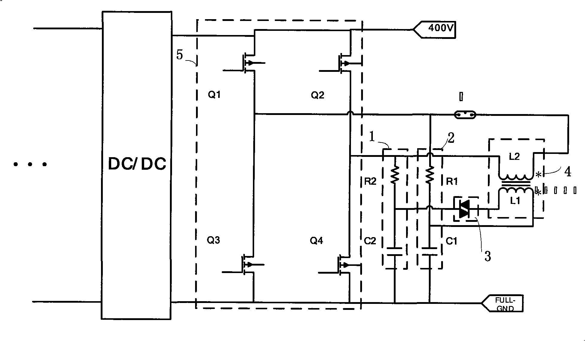
[0028] Embodiment 1, a kind of HID lamp electronic ballast ignition circuit control device (such as figure 1 shown), including Q 1 , Q 2 , Q 3 , Q 4 The composed full-bridge converter 5 includes two sets of RC charge-discharge circuits respectively connected between the midpoints of the two bridge arms of the full-bridge converter 5 and the ground, that is, the RC charge-discharge circuit I1 and the RC charge-discharge circuit II2 ; Also included with the capacitor C 1 , capacitance C 2 The gas discharge tube 3 and the ignition transformer 4 that make up the discharge circuit.

[0029] The RC charging and discharging circuit I1 consists of a series charging resistor R 1 and capacitance C 1 Composition, RC charging and discharging circuit II2 is composed of a series charging resistor R 2 and capacitance C 2 Composition; gas discharge tube 3 and primary side of ignition transformer 4 and capacitor C 1 and capacitance C 2 A series circuit is formed, and the secondary s...

Embodiment 2

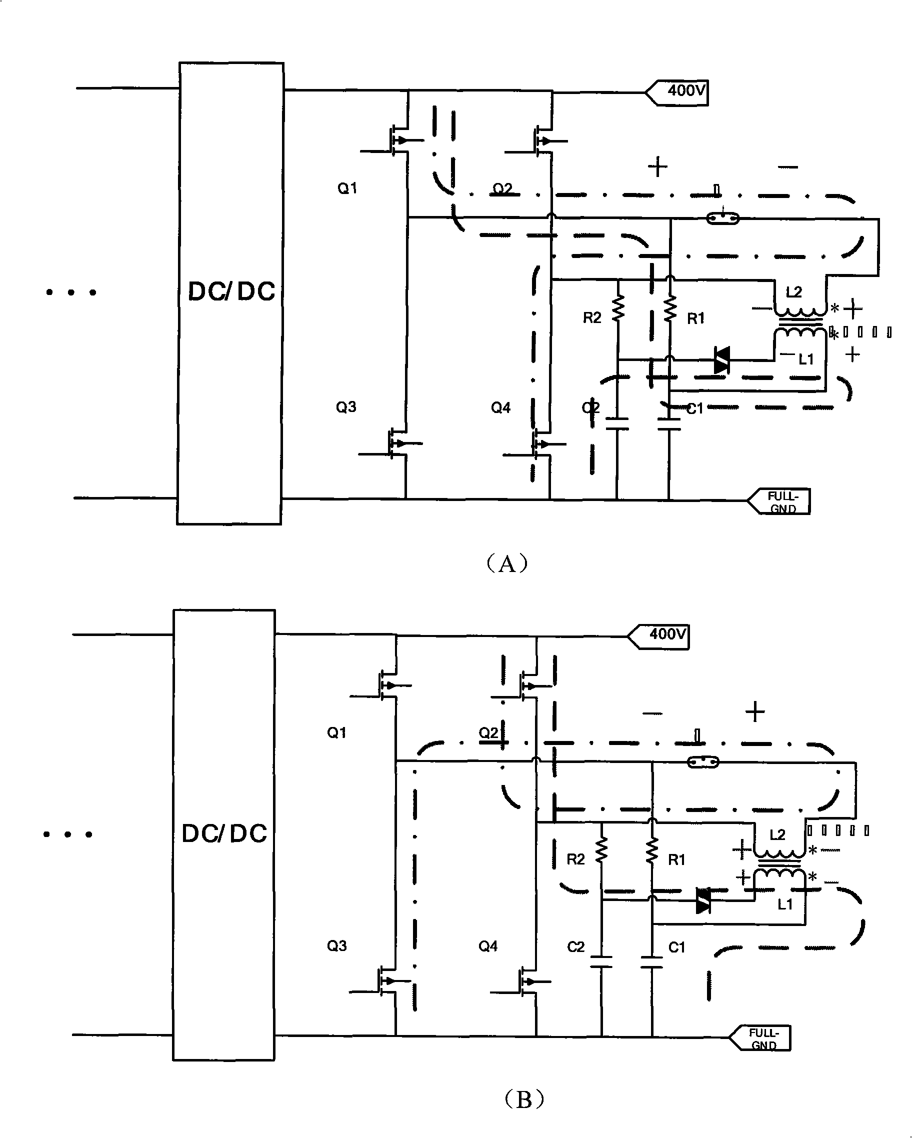
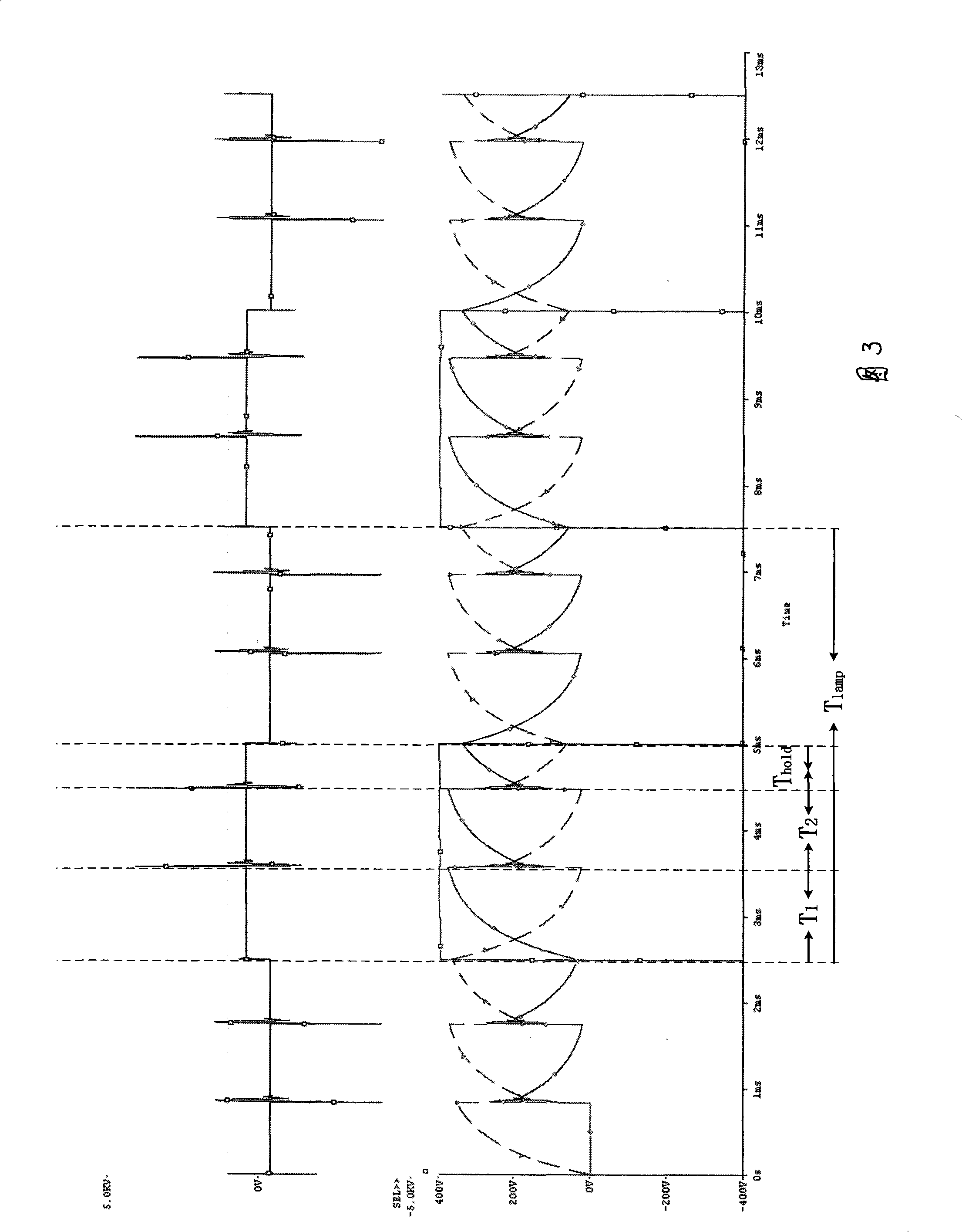
[0048] Embodiment 2, ignition pulse V pulse The phase of figure 2 The connection method shown in the figure strictly follows the output voltage of the inverter stage V dc The phase of , which ensures that the absolute value of each effective ignition pulse is V dc +V pulse . The dotted line in the figure represents the phase of the output voltage Vdc of the inverter stage, and the dotted line represents the high-voltage ignition pulse V pulse phase, it can be seen that when Q 1 , Q 4 When turned on, the bus voltage superimposed on both ends of the lamp tube is left + right -, at this time C 1 charging 2 Discharge, when the gas discharge tube 3 breaks down, the high-voltage pulse superimposed on both ends of the lamp tube is also left+right-, and the effective ignition voltage is V dc +V pulse .

[0049] On the contrary, when Q 2 , Q 3 When it is turned on, the bus voltage superimposed on both ends of the lamp is right+left-, at this time the capacitor C 2 Chargin...


PUM


Abstract

The invention discloses a pulse formula igniting controlling apparatus, which comprises groups of charging-discharge loops respectively connected between the two bridge arm middle points of a full bridge current transformer (5) and the earth: RC charging-discharge loop I (1) and RC charging-discharge loop II (2); also comprises a gas-discharge tube (3) and a igniting transformer (4) with accessory edge in serial connection with a HID lamp in the main circuit; the RC charging-discharge loop I (1) is composed of a charging resistor R1 and a capacitor C1 in serial connection, the RC charging-discharge loop II (2) is composed of a charging resistor R2 and a capacitor C2 in serial connection; the gas-discharge tube (3), primary side of the igniting transformer (4), the capacitor C1 and the capacitor C2 compose a serial connection loop. The invention further discloses a method for simple controllable sequential pulse type igniting control method using the above apparatus, and a igniting voltage superposing validity control method. The invention can solve the problems of ignition pulse sequential control and valid igniting voltage superposing at the same time.

Description

technical field [0001] The invention relates to an ignition circuit topology of an electronic ballast for an HID lamp, in particular to a high-efficiency pulse ignition circuit control method and a control device with simple and controllable timing and avoiding the phenomenon of reverse voltage pulse superposition. Background technique [0002] High-intensity discharge (HID) lamps have become the third-generation lighting source after incandescent lamps and fluorescent lamps due to their advantages such as high luminous efficiency and long life, and are playing an increasingly important role in the field of green lighting. Since the air pressure in the HID lamp is several times or even dozens of times the atmospheric pressure, it needs a breakdown voltage of several thousand volts or even tens of thousand volts to light it up. [0003] At present, most ignition circuits for HID lamps use two high-voltage ignition methods, pulse ignition and resonance ignition. The resonant ...

Claims


Application Information

Patent Timeline
Patent Type & Authority Patents(China)
IPC IPC(8): H05B41/14H05B41/36
CPCY02B20/204Y02B20/00
Inventor 陈敏马重光钱照明
Owner ZHEJIANG UNIV
Why Eureka
Try Eureka