Over-voltage protection device for limited installation space

A protection device, installation space technology, applied in overvoltage protection resistors, emergency protection devices, switches with overvoltage action, etc., can solve problems such as heating, large thermal energy, damage or fire

Active Publication Date: 2016-03-02
PHOENIX CONTACT GMBH & CO KG
View PDF8 Cites 0 Cited by
  • Summary
  • Abstract
  • Description
  • Claims
  • Application Information

AI Technical Summary

Problems solved by technology

[0004] Wherein the resulting thermal energy may be so great that electrical components and / or materials of the associated environment become so hot that damage or fire may result

Method used


Image

  • Over-voltage protection device for limited installation space
  • Over-voltage protection device for limited installation space

Examples


Embodiment Construction

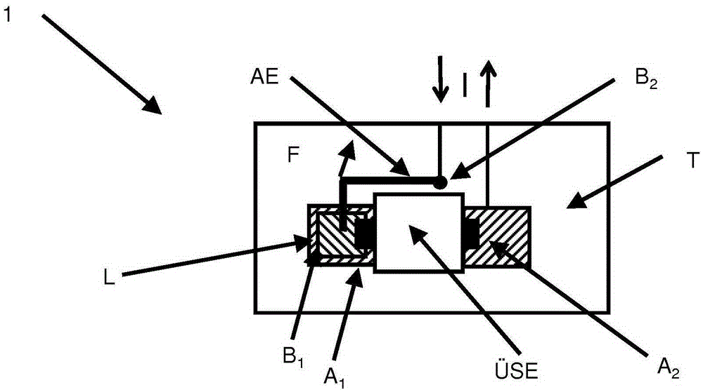
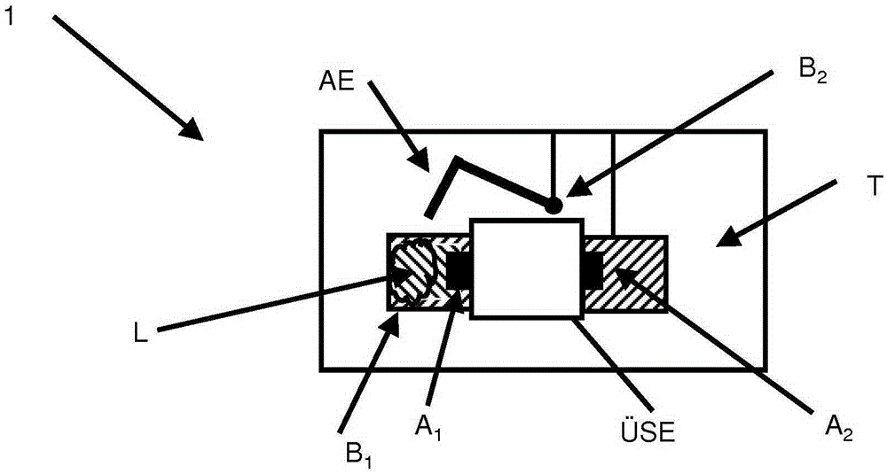
[0024] figure 1 with figure 2 An overvoltage protection device with limited installation space is shown. This overvoltage protection device has an isolator AE, the function of which will be explained further below.

[0025] In addition, the overvoltage protection device 1 limited in installation space also has a supporting body T. As shown in FIG.

[0026] Install an overvoltage protector with at least two interfaces A1, A2 on the support body T Wherein, the overvoltage protector The first interface, in this embodiment the interface A1, is in electrical contact with the disconnector AE in the untriggered state, so that the occurrence of overvoltage protection can pass through the overvoltage protector is exported.

[0027] In this untriggered state, the disconnector AE has a prestress F. Wherein, the disconnector AE is fixed on the interface B1 on the support body T and on the overvoltage protector by hot-melt fixing L. superior. This hot melt fixes L with the ove...


PUM


Abstract

The invention relates to an over-voltage protection device (1) for limited installation space, having an isolating apparatus (AE), having a carrier (T), wherein an over-voltage protection apparatus (uSE) having at least two connections (A1, A2) is attached to the carrier, wherein a first connection (A1; A2) of the over-voltage protection apparatus (uSE) contacts electrically via the isolating apparatus (AE) in the non-triggered state, so that an over-voltage protection event can be derived via the over-voltage protection apparatus (uSE), wherein the isolating apparatus (AE) is connected to a bias voltage (F) in the non-triggered state, wherein the isolating apparatus (AE) is thermally fixed (L) and wherein the thermal fixing is in thermal contact with the over-voltage protection apparatus (uSE) and wherein, upon reaching a predetermined temperature (Tswitch), the thermal fixing (L) softens so that, under the influence of the bias voltage (F), the isolating apparatus (AE) breaks the electrical contact, wherein the isolating apparatus (AE) is relocated under the influence of the bias voltage (F) to a plane substantially parallel to the surface of the carrier (T).

Description

technical field [0001] The invention relates to an overvoltage protection device limited in installation space. Background technique [0002] A large number of electrical components are known to enter into an operating state in the event of overload or improper loading in which they operate outside of a (specific) rated range. [0003] In such operating states, an undesired efficiency conversion often occurs, which leads to rapid heating of the electrical components themselves and the surrounding environment. [0004] In this case, the resulting thermal energy may be so great that electrical components and / or materials of the associated environment heat up in such a way that damage or a fire may result. [0005] So try to deal with these kind of temperature increases. [0006] For example, add a temperature insurance device to the overvoltage protection device. Contents of the invention [0007] A coupler for a thermal fuse is known from DE9010246U1. But the coupler re...

Claims


Application Information

Patent Timeline
Patent Type & Authority Applications(China)
IPC IPC(8): H01H85/02H01C7/12H01H85/36H01H83/10H01H85/00H01H85/048
CPCH01H85/0241H01C7/126H01H37/761H01H83/10H01H85/0052H01H85/36H01H2037/763H01H2085/0283H01H2085/0483H01H2085/0486
Inventor 托马斯·迈尔史蒂芬·波特
Owner PHOENIX CONTACT GMBH & CO KG
Why Eureka
Try Eureka