Numerical control hydraulic punching machine with follow-up material-pressing device

A pressing device and punching machine technology, applied in the direction of piercing tools, metal processing equipment, manufacturing tools, etc., can solve the problems of not being able to do it at the same time, long time, low production efficiency, etc., to reduce punching time and improve production efficiency , the effect of reducing production costs

Active Publication Date: 2016-03-09
JINAN EVERSHINING CNC MACHINE
View PDF5 Cites 1 Cited by
  • Summary
  • Abstract
  • Description
  • Claims
  • Application Information

AI Technical Summary

Problems solved by technology

In this punching, the pressing action and the punching action are performed separately, and the two actions cannot be performed at the same time, resulting in a long punching time and low production efficiency.

Method used


Image

  • Numerical control hydraulic punching machine with follow-up material-pressing device
  • Numerical control hydraulic punching machine with follow-up material-pressing device
  • Numerical control hydraulic punching machine with follow-up material-pressing device

Examples


Embodiment 1

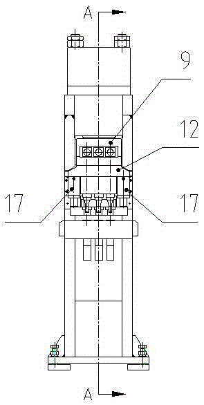
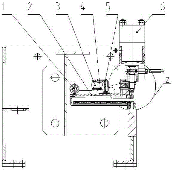
[0018] Two one-way pressing oil cylinders 17 are distributed on both sides of the punch rod guide seat 8, and the top of the cylinder body of the one-way pressing oil cylinder 17 is connected with the punch rod seat 12, and the punch rod seat 12 is connected with the press head 9 and the punching head. The oil cylinder 6 is connected as a whole, and the lower part of the piston rod of the one-way pressing oil cylinder 17 is close to the pressing frame 2. When the piston rod of the punching oil cylinder 6 moves downwards, the one-way pressing oil cylinder 17 can be driven by the pressing head 9 and the punch rod seat 12 to move downwards simultaneously and carry out pressing.

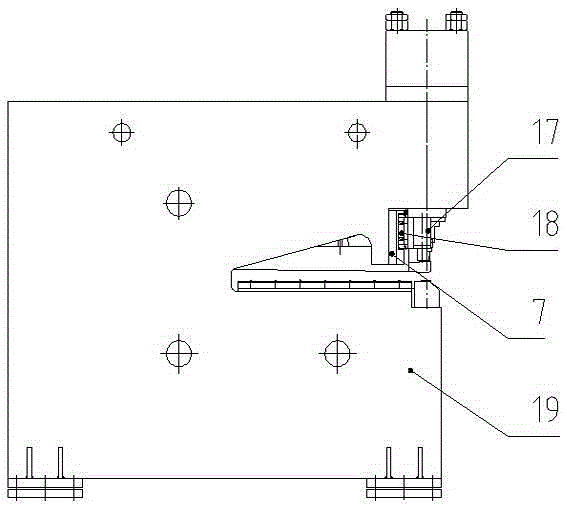
[0019] The one-way pressing oil cylinder 17 is fixed on the slide block of the linear guide rail 18, and the linear guide rail 18 is fixed on the guide seat plate 7, and the guide seat plate 7 and the fuselage 19 are fixed together. The two one-way pressing oil cylinders 17 can move accurately along the ...

Embodiment 2

[0025] One of them of two one-way pressure material oil cylinders 17 is arranged on the left side or the right side of the punch rod guide seat, and the other is arranged on the back of the punch rod guide seat. The top of the cylinder body of the one-way pressing oil cylinder 17 is connected with the punch rod seat 12, and the punch rod seat 12 is connected with the pressing head 9 and the punching oil cylinder 6 as a whole, and the piston rod of the one-way pressing oil cylinder 17 is connected with the lower pressing frame 2 close. When the piston rod of the punching oil cylinder 6 moves downwards, the one-way pressing oil cylinder 17 can be driven by the pressing head 9 and the punch rod seat 12 to move downwards simultaneously and carry out pressing.

[0026] The one-way pressing oil cylinder 17 is fixed on the slide block of the linear guide rail 18, and the linear guide rail 18 is fixed on the guide seat plate 7, and the guide seat plate 7 and the fuselage 19 are fixed ...


PUM


Abstract

The invention discloses a numerical control hydraulic punching machine with a follow-up material-pressing device. The numerical control hydraulic punching machine comprises a machine body, a punching oil cylinder, the follow-up material-pressing device, a punching head and a female die. The follow-up material-pressing device comprises a material-pressing frame and two one-way material-pressing oil cylinders. The material-pressing frame is rotatably installed on the machine body through an installing shaft. The one-way material-pressing oil cylinders are fixedly installed on the machine body through a guide base plate and fixed to a piston rod of the punching oil cylinder through a pressing head and a punching head rod base. The two one-way material-pressing oil cylinders are distributed on the two sides of a punching head rod guide base. The lower portions of piston rods of the one-way material-pressing oil cylinders are attached to the material-pressing frame tightly. The piston rod of the punching oil cylinder can drive the one-way material-pressing oil cylinders to move downwards. The punching head rod guide base is installed on the guide base plate. The punching head is fixedly installed on a punching head rod through a locking nut. The punching head rod is installed in the punching head rod base. The material-pressing frame is further provided with a material-pressing frame re-rising structure.

Description

technical field [0001] The invention relates to a numerically controlled hydraulic punching machine, in particular to a numerically controlled hydraulic punching machine with a follow-up pressing device. Background technique [0002] In the process of processing, when the existing numerical control hydraulic punching machine punches the workpiece blank, the control system of the numerical control hydraulic punching machine first sends out a signal, so that the pressing device of the numerical control punching machine first presses the workpiece blank, and then the numerical control hydraulic punching machine The control system of the punching machine sends out a signal again, and the punch is punched. When the punching is completed, the punch is pulled out from the workpiece and returns to its original position, and the control system sends out a signal again to lift the pressing device to complete the punching process. One punch. In this punching, the pressing action and t...

Claims


Application Information

Patent Timeline
Patent Type & Authority Applications(China)
IPC IPC(8): B21D28/34B21D37/12
CPCB21D28/34B21D37/12
Inventor 陈广先祝秀荣
Owner JINAN EVERSHINING CNC MACHINE
Why Eureka
Try Eureka