
A simulated mechanical finger based on electromagnetic drive

A mechanical finger, electromagnetic drive technology, applied in the directions of manipulators, chucks, manufacturing tools, etc., can solve the problems of inaccurate positioning of mechanical fingers, increased equipment weight, virtual swing of fingers, etc., to achieve convenient layout, good practical prospects, and simplification effect of structure

Active Publication Date: 2017-03-22
徐州振丰原喷灌设备有限公司
View PDF7 Cites 0 Cited by
  • Summary
  • Abstract
  • Description
  • Claims
  • Application Information

AI Technical Summary

Problems solved by technology

[0003] At present, the driving methods of manipulators mostly use servo motor drive, steel wire drive, hydraulic drive, etc., and a small part of them use artificial muscle drive; among them, artificial muscle drive, although the drive method is advanced, but the manufacturing cost is currently very high, and hydraulic drive requires powerful power. For hydraulic oil pressurized drive, it will increase the weight of the equipment and require higher technical maturity, so the cost is also higher; then, servo motor drive and wire drive are more common in the simulation manipulator drive, and the servo motor drive is used in each Install a servo motor on the joint, which will make the mechanism on the manipulator very unsightly. The size and shape of the servo motor will determine the shape and function of the manipulator; currently the most used and the lowest cost is to use steel wire drive to centrally install the servo motors At the arm, the mechanism of the manipulator and fingers is relatively simple, and the control is relatively easy. However, in the wire drive, it is easy to cause inaccurate positioning of the mechanical designation and swinging of fingers. Therefore, it is very important to design a low-cost and conveniently arranged drive method. necessary

Method used


Image

  • A simulated mechanical finger based on electromagnetic drive
  • A simulated mechanical finger based on electromagnetic drive
  • A simulated mechanical finger based on electromagnetic drive

Examples


Embodiment Construction

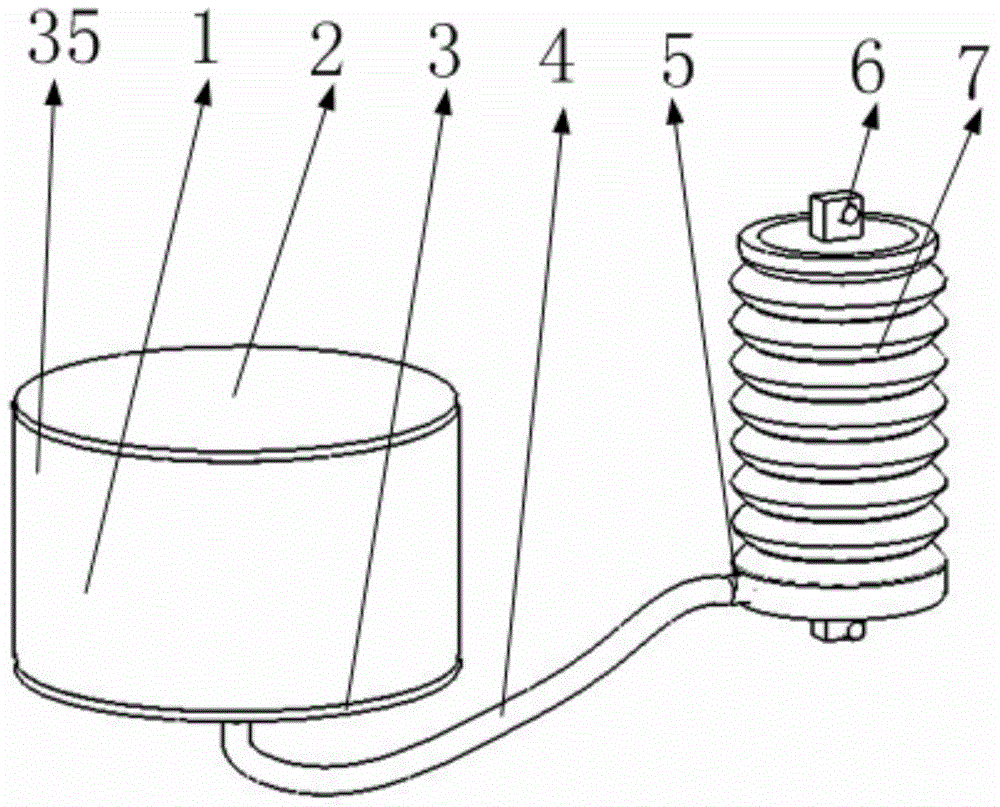
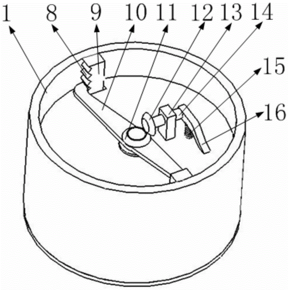
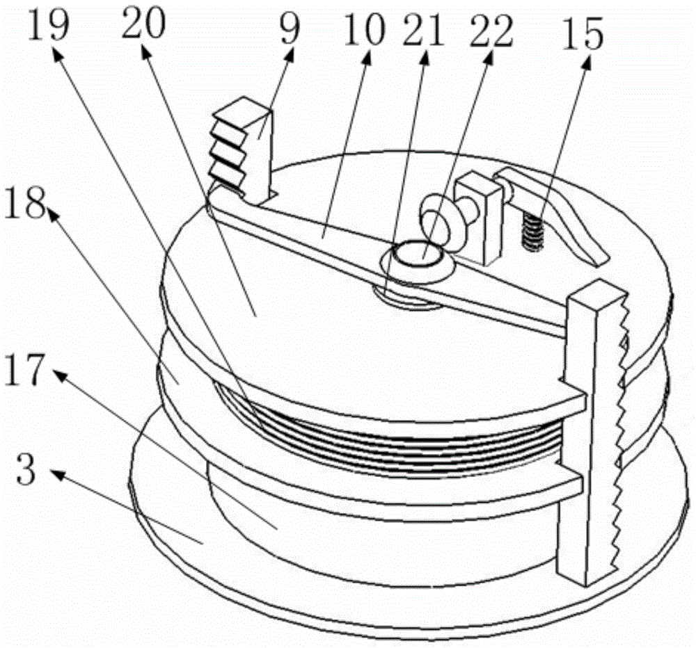
[0036] Such as Figure 15 As shown, it includes the fourth bracket of the mechanical finger, the third bracket of the mechanical finger, the second bracket of the mechanical finger, the first bracket of the mechanical finger, the support of the execution unit, the limit plate of the mechanical finger bracket, the third return spring of the mechanical finger, the second mechanical finger Two return springs, the first return spring of the mechanical finger, the support of the return spring of the mechanical finger, the lug of the execution unit, the power unit, the execution unit, and the liquid medium conduit, such as Figure 16 As shown, the second bracket of the mechanical finger is installed on the first bracket of the mechanical finger through a cylindrical pin, the third bracket of the mechanical finger is installed on the second bracket of the mechanical finger through a cylindrical pin, and the fourth bracket of the mechanical finger is installed on the second bracket of ...


PUM


Abstract

The invention belongs to the technical field of simulation mechanical arm drive and particularly relates to a simulation mechanical finger based on electromagnetic drive. The simulation mechanical finger based on electromagnetic drive comprises a power unit, executing units, a liquid medium guide pipe, mechanical finger supports, mechanical finger reset springs and the like. The power unit is connected with the executing units at three joints of the mechanical finger through the liquid medium guide pipe, pressure and attraction force on a liquid medium are generated through attraction and rejection of the magnetism of an electromagnetic structure in the power unit and the magnetism of a magnetic bottom cover of the power unit, and thus the purposes of controlling the length of the executing units and driving a mechanical arm to move and change are achieved. In addition, the three executing units are driven through the same power unit, so that the pressure of the liquid medium in the executing units is the same, and it can be ensured that the mechanical finger can better adapt to the appearance of a grabbed object; the guide pipe is used for transmitting pressure so that the executing units can be conveniently arranged, the structure of the mechanical arm can be greatly simplified, and good practical prospects are achieved.

Description

[0001] Technical field [0002] The invention belongs to the technical field of simulation manipulator drive, and in particular relates to a simulation manipulator finger based on electromagnetic drive. Background technique [0003] At present, the driving methods of manipulators mostly use servo motor drive, steel wire drive, hydraulic drive, etc., and a small part of them use artificial muscle drive; among them, artificial muscle drive, although the drive method is advanced, but the manufacturing cost is currently very high, and hydraulic drive requires powerful power. For hydraulic oil pressurized drive, it will increase the weight of the equipment and require higher technical maturity, so the cost is also higher; then, servo motor drive and wire drive are more common in the simulation manipulator drive, and the servo motor drive is used in each Install a servo motor on the joint, which will make the mechanism on the manipulator very unsightly. The size and shape of the ser...

Claims


Application Information

Patent Timeline
Patent Type & Authority Patents(China)
IPC IPC(8): B25J15/08
CPCB25J15/0009
Inventor 何莹
Owner 徐州振丰原喷灌设备有限公司
Learn More