Bioreactor

A bioreactor and tank technology, used in bioreactor/fermenter combinations, specific-purpose bioreactors/fermenters, biochemical instruments, etc. Cleaning dead corners and other problems, to achieve the effect of fast liquid addition, no cleaning dead corners, and no residual liquid

Inactive Publication Date: 2016-03-09
NINGBO DINGYUAN SOFTWARE TECH CO LTD
View PDF0 Cites 0 Cited by
  • Summary
  • Abstract
  • Description
  • Claims
  • Application Information

AI Technical Summary

Problems solved by technology

[0004] The object of the present invention is to provide a bioreactor, by setting up the improved liquid feeding pipeline, realize the liquid feeding mode attached to the wall, and solve the problem of using liquid feeding directly from the top of the

Method used


Image

  • Bioreactor

Examples


Embodiment Construction

[0011] The principles and features of the present invention are described below in conjunction with the accompanying drawings, and the examples given are only used to explain the present invention, and are not intended to limit the scope of the present invention.

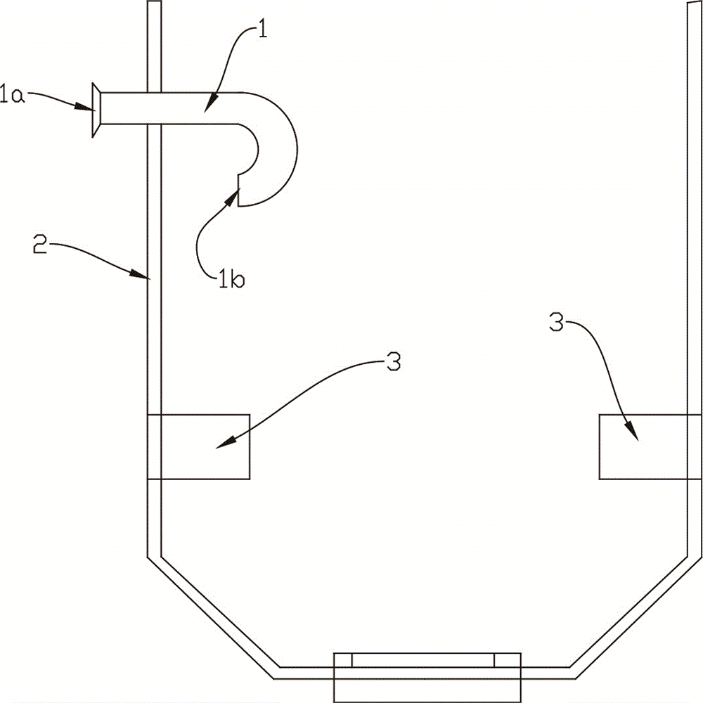
[0012] In the prior art, the liquid feeding pipeline of the bioreactor usually uses a pipe directly extending from the top of the tank to the bottom of the tank. Such a structure will generate many bubbles when adding liquid, which will damage the cells and form There are problems such as cleaning dead ends, residual liquid remaining in pipes, and difficult installation.

[0013] The bioreactor of the present invention can realize the way of adding liquid attached to the wall, and reduce the generation of air bubbles when adding liquid. See figure 1 , the bioreactor of the present invention comprises a tank body 2 and a liquid-feeding pipeline 1, wherein the liquid-feeding pipeline 1 is fixed on the top of the tank...


PUM


Abstract

The invention discloses a bioreactor. The bioreactor comprises a tank and a liquid adding pipe. The liquid adding pipe is fixed to the upper portion of the tank, a liquid inlet of the liquid adding pipe extends out of the tank, a liquid outlet of the liquid adding pipe is located in the tank and faces the inner wall of the tank, and two heating modules are further symmetrically arranged in the tank. According to the bioreactor, culture liquid can flow to the bottom of the tank along the inner wall of the tank when added, and bubbles are effectively reduced; in addition, the bioreactor has the advantages of being convenient to install, high in liquid adding speed, free of residual liquid, free of cleaning dead angles and the like.

Description

technical field [0001] The invention relates to a bioreactor and belongs to the field of biotechnology. Background technique [0002] The liquid feeding pipeline of the bioreactor is used to supplement the culture medium, inoculate cells, etc. into the tank of the bioreactor. The volume of cell culture medium or inoculated cell suspension required in large bioreactors is large, so it is necessary to use pipelines with large inner diameters such as DN25 or DN40. [0003] The liquid feeding pipeline of the traditional bioreactor usually uses a pipe directly from the top of the tank to the bottom of the tank. If this traditional liquid feeding method is followed, there may be the following problems: 1) The inside of the tank will increase the amount of dirt that is difficult to clean. 2) After adding liquid, some residual liquid may remain inside the liquid feeding pipe to form a dead area, which cannot effectively fuse with the cells outside the liquid feeding pipe; 3) Due to...

Claims


Application Information

Patent Timeline
IPC IPC(8): C12M1/00
CPCC12M29/00C12M41/24
Inventor 张勤洲
Owner NINGBO DINGYUAN SOFTWARE TECH CO LTD
Why Eureka
Try Eureka