Lamination apparatus

a technology of lamination apparatus and nozzle, which is applied in the direction of chemistry apparatus and processes, identification means, instruments, etc., can solve the problems of air bubbles being generated between the display panel and the window

Active Publication Date: 2022-11-01
SAMSUNG DISPLAY CO LTD
View PDF25 Cites 0 Cited by
  • Summary
  • Abstract
  • Description
  • Claims
  • Application Information

AI Technical Summary

Benefits of technology

[0007]According to an aspect of embodiments of the present invention, a lamination apparatus may reduce air bubbles generated during coupling a display panel to a window. According to another aspect of embodiments of the present invention, a lamination apparatus including a heating member is provided.
[0034]According to an aspect of embodiments of the present invention, a lamination apparatus includes a window jig for supporting the window to be coupled to the display panel. The window jig may include a heating member partially heating the window jig (such as a cartridge heater, a ceramic heater, and an infrared lamp). Due to the heating member, when the window disposed in the window jig is coupled to the display panel the lamination apparatus can minimize or reduce the generation of air bubbles between the window and the display panel. In addition, due to the heating member, the lamination apparatus can effectively couple the window and the display panel even when a low pressure is applied.

Problems solved by technology

However, air bubbles may be generated between the display panel and the window during coupling the display panel to the window.

Method used


Image

  • Lamination apparatus
  • Lamination apparatus
  • Lamination apparatus

Examples


Embodiment Construction

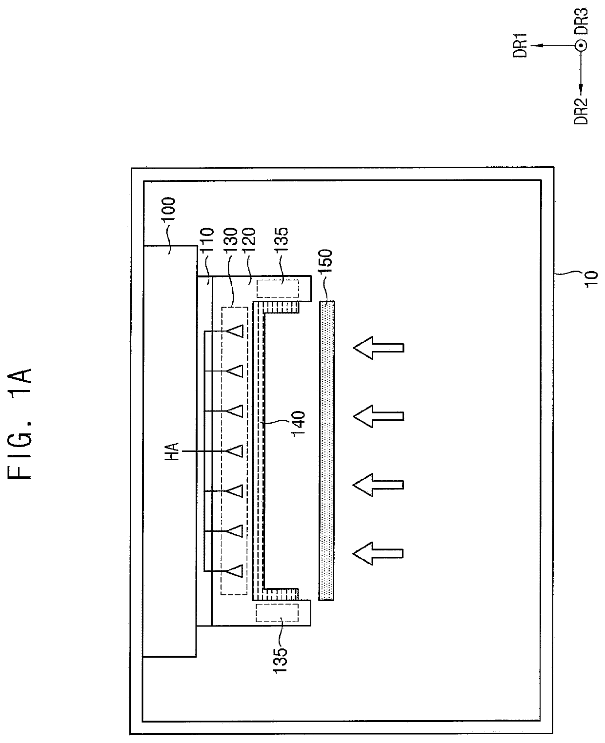
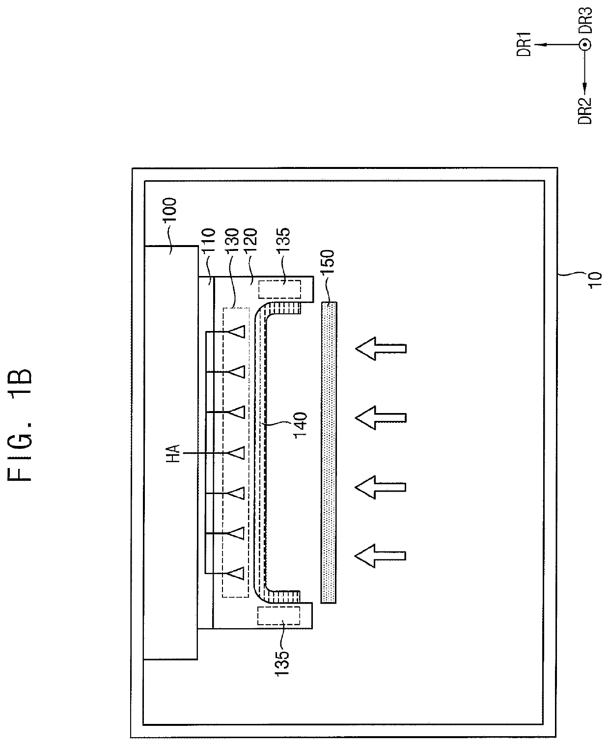
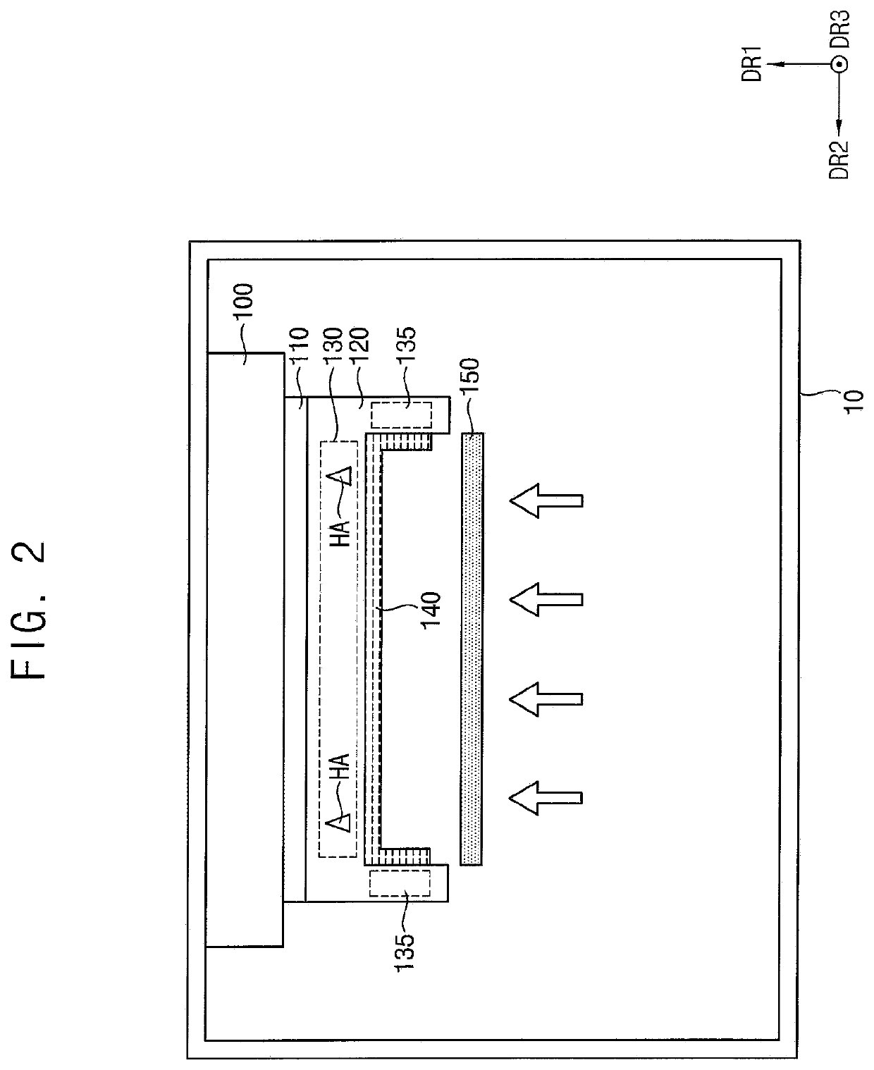
[0052]Herein, some embodiments of the present invention will be described in further detail with reference to the accompanying drawings. The inventive concepts may, however, be embodied in many different forms, and should not be construed as limited to the embodiments set forth herein. The same reference numerals are used for the same components in the drawings, and redundant descriptions of the same components may be omitted. In the drawings, the thickness, ratio, and dimensions of components may be exaggerated for ease of description of the technical content.

[0053]In the present disclosure, it is to be understood that when an element or layer is referred to as being “on,”“connected to,” or “coupled to” another element or layer, it may be directly on, connected, or coupled to the other element or layer, or one or more intervening elements or layers may be present.

[0054]It is to be understood that, although the terms “first,”“second,” etc. may be used herein to describe various elem...


PUM

PropertyMeasurementUnit
areaaaaaaaaaaa
electrical resistanceaaaaaaaaaa
pressureaaaaaaaaaa

Abstract

A lamination apparatus includes: a window jig to support a window, and a heating member in the window jig to partially heat the window jig. The window jig includes a flat portion including a first sidewall area, a second sidewall area facing the first sidewall area in a first direction, a third sidewall area perpendicular to the first sidewall area, and a fourth sidewall area perpendicular to the first sidewall area and facing the third sidewall area in a second direction perpendicular to the first direction, a first protrusion portion protruding in a third direction perpendicular to the first and second directions on the first sidewall area, and a second protrusion portion protruding in the third direction on the second sidewall area.

Description

CROSS-REFERENCE TO RELATED APPLICATIONS[0001]This application claims priority to and the benefit of Korean Patent Application No. 10-2020-0083731, filed on Jul. 7, 2020, and Korean Patent Application No. 10-2020-0161695, filed on Nov. 26, 2020, in the Korean Intellectual Property Office, the entire disclosure of each of which is hereby incorporated by reference.BACKGROUND1. Field[0002]Aspects of embodiments of the present invention relate to a lamination apparatus.2. Discussion of the Background[0003]Recently, as interest in display devices increases, various studies on the display device have been conducted. Accordingly, the display device has been manufactured in various types including organic light emitting diodes (OLED) and liquid crystal displays (LCD).[0004]The display device may provide various images to a user through a display panel. The display device may include a window for protecting the display panel. The window may be coupled to the display panel while covering the d...

Claims


Application Information

Patent Timeline
Patent Type & Authority Patents(United States)
IPC IPC(8): B29C65/00B32B37/00B32B37/10B32B37/06B29C65/18
CPCB32B37/0046B32B37/06B32B37/10B29C65/00B29C65/18B29C66/43B32B37/0076B32B2457/20G09F9/35H10K59/10B32B37/003
Inventor SIM, JAEYOUNGKIM, SOHYUNHAN, NIEL
Owner SAMSUNG DISPLAY CO LTD
Why Eureka
Try Eureka