A battery cover installation structure

A technology for installing structures and battery covers, which is applied to structural parts, battery boxes/coats, battery pack components, etc., can solve the problems of inconvenient battery replacement, and achieve the effects of easy replacement, convenient opening and closing, and good three-proof performance

Active Publication Date: 2018-10-16
GUANGZHOU SOUTH SATELLITE NAVIGATION INSTR
View PDF6 Cites 0 Cited by
  • Summary
  • Abstract
  • Description
  • Claims
  • Application Information

AI Technical Summary

Problems solved by technology

When the battery cover module 10 is closed, it is only necessary to press the battery cover module 10 downward, so that the left and right buckles 11, 12 of the battery cover module 10 are fastened to the cavity 15 slot by the elastic force of the compression spring 13, and the battery The inner wall of the cover module 10 compresses the waterproof ring 14 to achieve the purpose of waterproofing; when the battery cover module 10 is disassembled, the left and right buckles 11 and 12 need to be pressed to the middle at the same time, so that the left and right buckles 11 and 12 are separated from the slots of the cavity 15 At the same time, force is applied upwards to overcome the friction between the waterproof ring 14 and the inner wall of the battery cover module. Due to this, the force required to be applied is relatively large, especially when used in a low temperature environment, it will be difficult for the user when replacing the battery. cause great inconvenience

Method used


Image

  • A battery cover installation structure
  • A battery cover installation structure
  • A battery cover installation structure

Examples


Embodiment Construction

[0025] Hereinafter, the present invention will be further described with reference to the drawings and specific implementations:

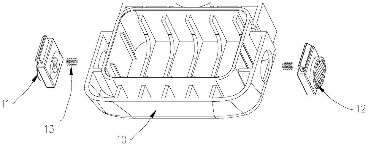
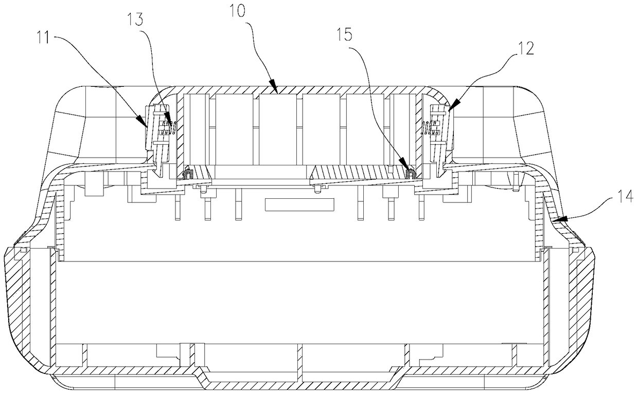
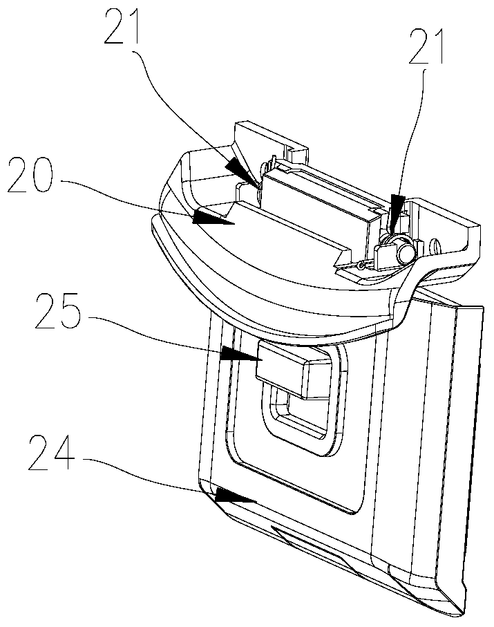
[0026] Such as Figure 3-6 The battery cover installation structure shown includes a battery cover 24, an elastic mechanism, a shift lever 25, a sealing component and a fixing seat 20. One end of the battery cover 24 is hinged to the fixing seat 20, and one end of the shift lever 25 is provided with a battery cover The dial key 253 protruding from the outer side of the 24. The other end of the dial lever 25 is provided with a buckle 251 protruding to the inside of the battery cover 24. The battery cover 24 has an opening 242 for the dial key 253 to pass through. The opening 242 has A toggle space for the dial key 253 to move along the direction between the two ends of the battery cover 24; an elastic mechanism is connected between the battery cover 24 and the shift lever 25 for providing the shift lever 25 with one end facing the battery cover 24 The...


PUM


Abstract

The invention discloses a battery cover installation structure, which comprises a battery cover, an elastic mechanism, a driving rod, a sealing assembly and a fixing seat, one end of the battery cover is hinged to the fixing seat, and one end of the driving rod is provided with a To dial the key, the other end of the shift lever is provided with a buckle protruding to the inside of the battery cover, and the battery cover has an opening for the dial key to pass through, and the opening has a function for the dial key to move along the direction between the two ends of the battery cover The toggle space; the elastic mechanism is connected between the battery cover and the lever, and is used to provide elastic stress for the lever to move toward one end of the battery cover; the sealing assembly is sealed on the inside of the battery cover, and is surrounded by the battery cover combined to form an accommodating space for accommodating the lever. The invention can facilitate the opening and closing of the battery cover, thereby facilitating the replacement of the battery, and at the same time can ensure better three-proof effects.

Description

Technical field [0001] The invention relates to a battery cover structure, in particular to a battery cover installation structure with three protection functions. Background technique [0002] Real-time dynamic control system (RTK, Real-time kinematic) is a commonly used GPS measurement method, and its measurement equipment is often operated outdoors. Therefore, RTK measurement equipment has higher requirements for battery life, battery replacement and three preventions. [0003] Such as figure 1 Shown is an exploded view of the battery cover module commonly used in RTK measurement equipment, such as figure 2 It is a cross-sectional schematic diagram of the battery cover module after the cavity is covered. Among them, 10, battery cover module, 11, left buckle, 12, right buckle, 13, spring, 14, waterproof ring, 15, cavity. When the battery cover module 10 is closed, you only need to press the battery cover module 10 down so that the left and right buckles 11 and 12 of the battery ...

Claims


Application Information

Patent Timeline
Patent Type & Authority Patents(China)
IPC IPC(8): H01M2/04H01M2/08H01M50/262H01M50/271
CPCH01M50/166H01M50/171H01M50/183Y02E60/10
Inventor 徐镇忠赵瑞东曾祥华闫少霞文述生马原
Owner GUANGZHOU SOUTH SATELLITE NAVIGATION INSTR
Why Eureka
Try Eureka