Automatic telescopic type head band structure

A technology of automatic telescopic and telescopic belts, which is applied to the fastening devices of head coverings, clothing, eye masks, etc., can solve the problems of uneven head size, increased mask damage, and high price, so as to meet safety requirements, Ease of fast protection and short wearing time

Inactive Publication Date: 2016-03-16
TECMEN ELECTRONICS
View PDF12 Cites 13 Cited by
  • Summary
  • Abstract
  • Description
  • Claims
  • Application Information

AI Technical Summary

Problems solved by technology

[0005] In order to solve the problem of inconsistencies in wearing tightness caused by different head sizes of the wearer, the head circumference structure of the prior art usually adopts a manual adjustment structure to adjust the headband structure when wearing it.
But, the problem of this manual adjustment: First, the suitable degree of each manual adjustment is closely related to the proficiency of the wearer, if the headband structure is adjusted too tightly on the head, then although the mask shell can be adjusted relative to the head Stable positioning and thus provide protection against external impact, but the wearer will be prone to faint due to blood congestion due to the pressure of the headband structure on the head after working for a long time; second, if the wearer adjusts the headband structure on his head too loosely, the Although the wearer does not feel discomfort, the mask shell is not firmly positioned relative to the head and thus does not provide adequate impact protection from external forces
[0006] In addition, for some special masks (such as welding masks), due to the professional design of the mask itself and the relatively expensive reasons, often one mask will be equipped with multiple operators.
In this case, in addition to the problems noted above, the manual adjustment of the headgear structure between different wearing operators also increases the possibility of mask damage

Method used


Image

  • Automatic telescopic type head band structure
  • Automatic telescopic type head band structure
  • Automatic telescopic type head band structure

Examples


Embodiment Construction

[0032] In the various figures of the application, structurally identical or functionally similar features are indicated by the same reference numerals.

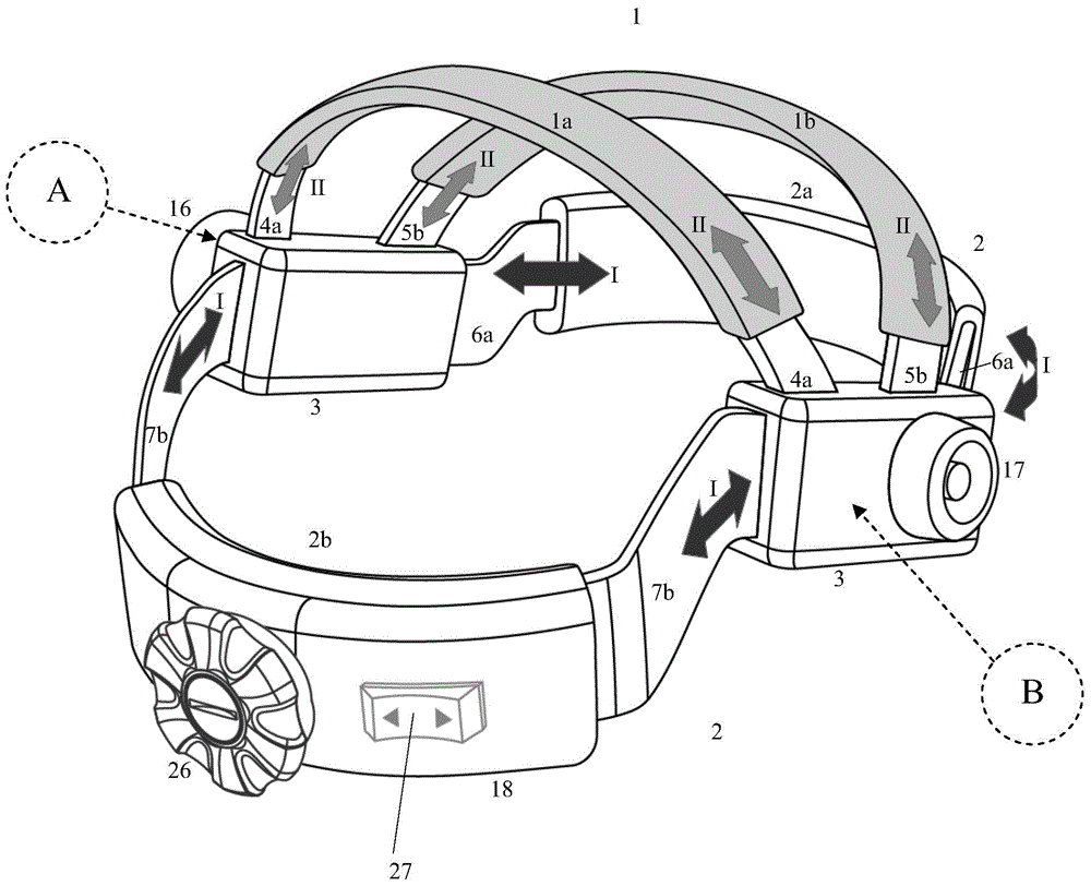
[0033] The following content of the manual is only for the description of the headband structure of the mask. It should be apparent to those skilled in the art that the headgear structure of the present invention is suitable for application in any suitable mask, such as a welding mask. The headband structure is fixed on the inner liner of the mask, and the specific fixing method is based on any means known to those skilled in the art, and will not be repeated here.

[0034] Such as figure 1 As shown, the headband structure generally includes a head restraint part 1 and a head circumference restraint part 2 . The head restraint part 1 is mainly used to provide the tightening force of the headband structure on the top of the wearer's head, while the head circumference restraint part 2 is mainly used to provide the tightening ...


PUM


Abstract

The invention provides a head band structure, in particular to a head band structure of a face mask. The head band structure comprises a head top restraint part used for being attached to the top of the head of a wearer when the face mask is worn, a head circumference restraint part used for being attached to the forehead and the back side of the head when the face mask is worn and a middle connection part connected between the head top restraint part and the head circumference restraint part, wherein the head top restraint part is provided with at least two mutually spaced telescopic bands, each telescopic band can be controlled to be automatically stretched out and drawn back relative to the middle connection part, the head circumference restraint part comprises a front restraint band used for being attached to the forehead and a rear restraint band used for being attached to the back side of the head, and the front restraint band and the rear restraint band can be controlled to be automatically stretched out and drawn back relative to the middle connection part. The invention further relates to the face mask with the head band structure.

Description

technical field [0001] The present invention relates generally to headgear structures, particularly headgear structures for use in protective masks such as welding helmets. Background technique [0002] Typically, a headgear structure is lined within a protective mask, such as a welding mask. When the mask is in place, the headgear structure is in direct contact with the wearer's head and is positioned between the wearer's head and the mask shell for secure positioning of the mask shell relative to the wearer's head. [0003] The headgear structure generally includes a crown restraint portion for providing restraint to the headgear structure around the wearer's forehead and back of the head, and a head circumference restraint portion for providing headgear structure attachment A binding on the top of the wearer's head. [0004] For safety reasons, the headband structure of the mask must require all parts to be close to the wearer's head with an appropriate force when worn,...

Claims


Application Information

Patent Timeline
Patent Type & Authority Applications(China)
IPC IPC(8): A61F9/06A42B7/00
Inventor 吴子乾
Owner TECMEN ELECTRONICS
Why Eureka
Try Eureka