
Wireless power transmitter capable of automatic adjustment according to impedance change

a technology of automatic adjustment and impedance change, applied in the direction of transmission, electrical equipment, circuit arrangement, etc., can solve the problem of not easy to realize a circuit capable of accurately detecting the phase, and achieve the effect of protecting the output power, smooth transmission output power, and complicated and precise impedance detection circuits

Active Publication Date: 2020-08-27
MAPS
View PDF0 Cites 18 Cited by
  • Summary
  • Abstract
  • Description
  • Claims
  • Application Information

AI Technical Summary

Benefits of technology

The present invention allows for quick protection of switches and the simplification of impedance detection circuits. This is done by detecting the hard switching state of the switch and performing auto-tuning. Auto-tuning is also achieved without measuring the phase information of the resonator, which allows for smoother transmission of output power.

Problems solved by technology

However, with the technique of A4WP, it is not easy to realize a circuit capable of accurately detecting the phase because the resonance frequency of the resonator is as high as 6.78 MHz and the voltage of the resonator can reach several hundreds of volts.

Method used

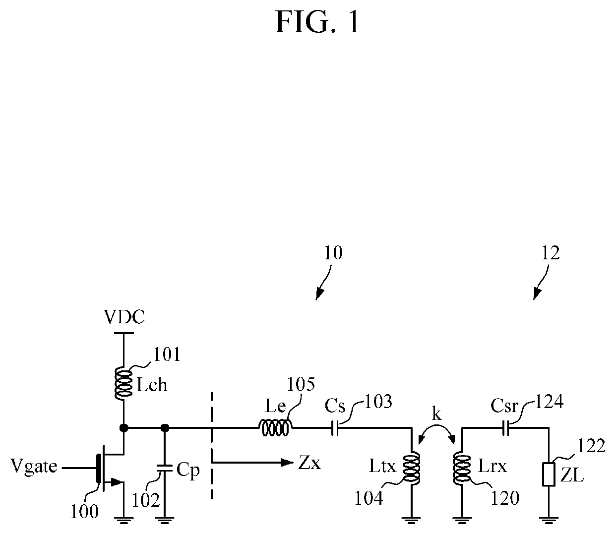
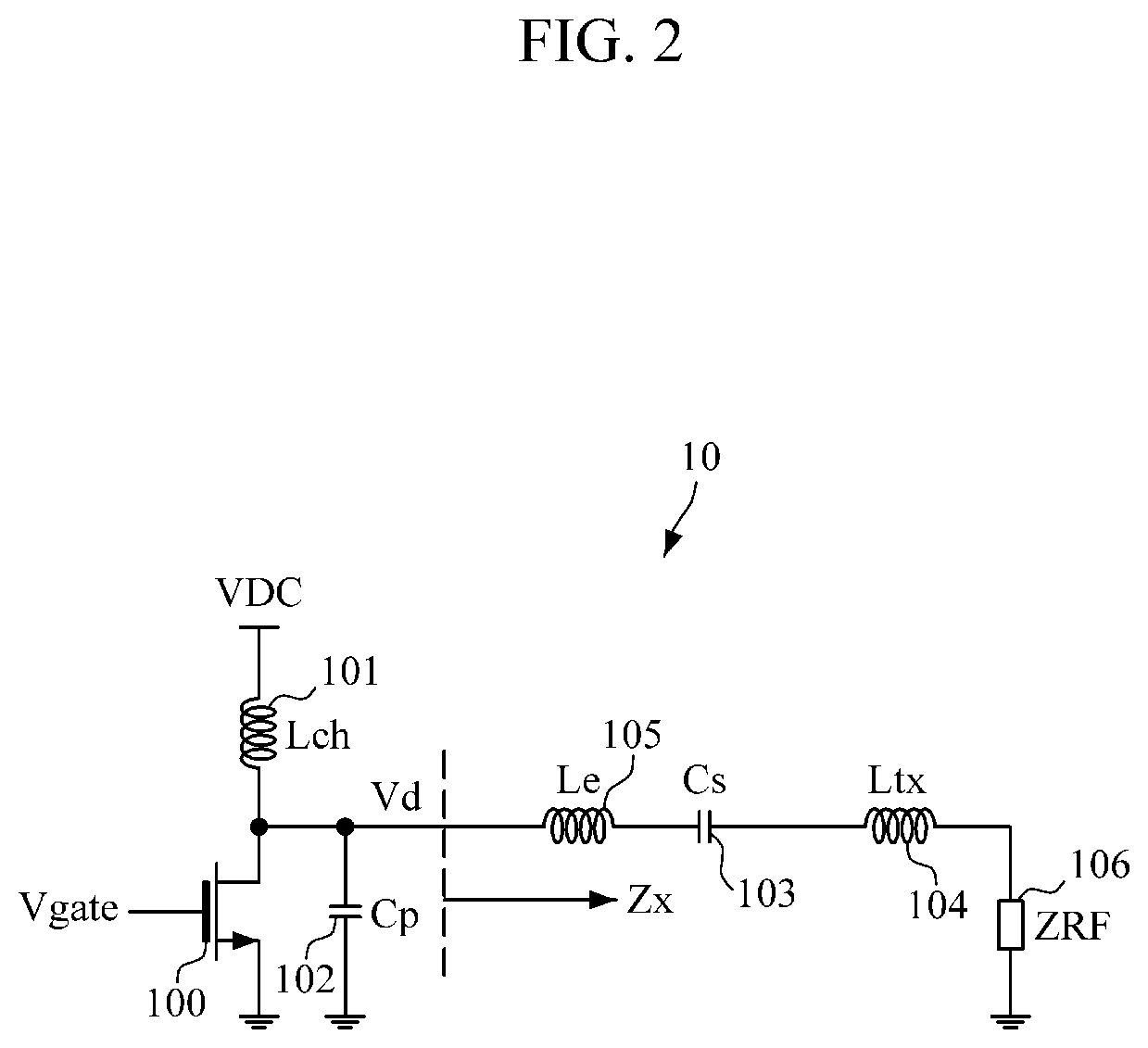
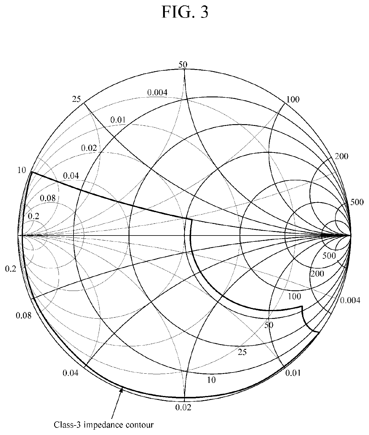

Image

  • Wireless power transmitter capable of automatic adjustment according to impedance change
  • Wireless power transmitter capable of automatic adjustment according to impedance change
  • Wireless power transmitter capable of automatic adjustment according to impedance change

Examples


Embodiment Construction

[0027]Advantages and features of the present invention and methods to achieve the same will become apparent from the detailed descriptions of exemplary embodiments herein below with reference to the accompanying drawings. The present invention may, however, be embodied in many different forms and should not be construed as being limited to the embodiments set forth herein. Rather, these embodiments are provided so that this disclosure will be thorough and complete and will fully convey the concept of the invention to those skilled in the art. The present invention is only defined by the claims. Like reference numerals designate like elements throughout the specification.

[0028]In the following description of exemplary embodiments of the present invention, a detailed description of known functions and configurations incorporated herein will be omitted when it may make the subject matter of the present invention rather unclear. The terms described below are defined in consideration of ...


PUM


Abstract

Provided is a wireless power transmitting unit capable of auto-tuning according to impedance change. The wireless power transmitting unit according to an embodiment can stabilize the operation of the amplifier by changing the resonance frequency of the resonator without measuring the phase information about the resonator.

Description

TECHNICAL FIELD[0001]The present invention relates to wireless power transmission and reception techniques.BACKGROUND ART[0002]In Alliance for Wireless Power (A4WP), which is a wireless charging standard using a frequency of 6.78 MHz, the impedance of a load is reflected in a wireless power transmitting unit (PTU), and therefore the operation point and output power of an amplifier constituting the PTU are determined by the impedance of the load. Accordingly, an auto-tuning circuit for tuning a resonator according to the impedance of the reflected load to ensure a stable operation point and smoothly transmit the output power is required.[0003]There is a technique for detecting a voltage / current of the resonator to determine the phase and operate the resonator such that the resonator has a similar resonance point according to change in impedance of the load. However, with the technique of A4WP, it is not easy to realize a circuit capable of accurately detecting the phase because the r...

Claims


Application Information

Patent Timeline
Patent Type & Authority Applications(United States)
IPC IPC(8): H02J50/12H04B5/00H02J50/70H02J50/80
CPCH02J50/70H02J50/80H02J50/12H04B5/0031H02J50/20H04B5/72H02J50/90H04B5/79
Inventor HWANG, JONG TAEJEON, IK SOOLEE, DONG SUSHIN, HYUN ICKRHEE, JOON
Owner MAPS
Learn More