
Rapid clamping device for pipeline cleaning machine

A pipeline cleaning and clamping device technology, which is applied in the direction of cleaning hollow objects, cleaning methods and utensils, chemical instruments and methods, etc., can solve the corrosion of screw rods and guide rods, is not suitable for cleaning large batches of pipe fittings, cleaning liquid spraying Reliable and stable clamping force can be achieved without problems such as

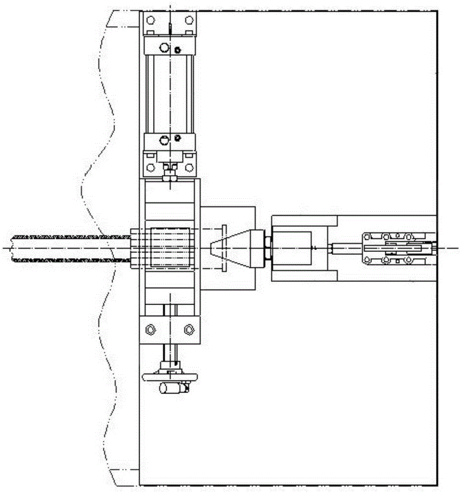
Inactive Publication Date: 2016-03-16
全加机械设备(上海)有限公司
View PDF5 Cites 2 Cited by
  • Summary
  • Abstract
  • Description
  • Claims
  • Application Information

AI Technical Summary

Problems solved by technology

The disadvantages are: first, the adjustment of the screw rod is time-consuming and laborious
For different types of pipe fittings, especially those with a relatively large diameter difference, the screw needs to be turned during the switching operation; because the driving speed of the screw is very slow, it is necessary to turn the hand wheel many times repeatedly to adjust to a roughly suitable position. product is a waste of time
Second, the centering effect is very bad
It is difficult to control the axis of the pipe fitting and the axis of the nozzle by human eyes; and each operator feels differently, so it is very likely that there will be a gap between the nozzle and the pipe joint during cleaning. As a result, the cleaning fluid is sprayed out, which requires the operator to repeatedly adjust the center position
Third, it is not conducive to the cleaning of large quantities of pipe fittings
As for whether the contact between the nozzle and the pipe joint is reliable, it needs to be adjusted repeatedly during operation, and every time the pipe is changed, it needs to be readjusted. This is a time-consuming, laborious and inhumane operation, especially not suitable for large-scale pipe cleaning.
Fourth, it is not suitable for products with a large change in the length of the pipe joint
The disadvantages are: first, the adjustment of the screw rod is time-consuming and laborious
The movement of the splint needs to turn the screw. For different types of pipe fittings, especially those with large diameter differences, it is troublesome to turn the screw when switching operations.
Second, it is not conducive to the cleaning of large quantities of pipe fittings
Even to clean the same type of pipe fittings, it is necessary to turn the hand wheel repeatedly to open or clamp the splint. The operation is too cumbersome, time-consuming and labor-intensive, and it is not humanized
Third, it is not suitable for products with large changes in the length of the pipe joint
Since the quick clamp is directly fixed, when there is a relatively long joint or a very short joint, the shaft of the clamp may not be fully extended or extended to the bottom, and the nozzle cannot be pushed against the joint of the pipe. Because the position of the splint clamping the pipe cannot be very random, that is to say, the pipe to be cleaned cannot be easily moved in the axial direction to meet the position of the nozzle.
Fourth, easy to rust
Since both the screw and the guide rod are under the pipe, if the cleaning fluid is tap water, the screw and the guide rod will soon be corroded and the rotation will be inflexible

Method used


Image

  • Rapid clamping device for pipeline cleaning machine
  • Rapid clamping device for pipeline cleaning machine
  • Rapid clamping device for pipeline cleaning machine

Examples


Embodiment Construction

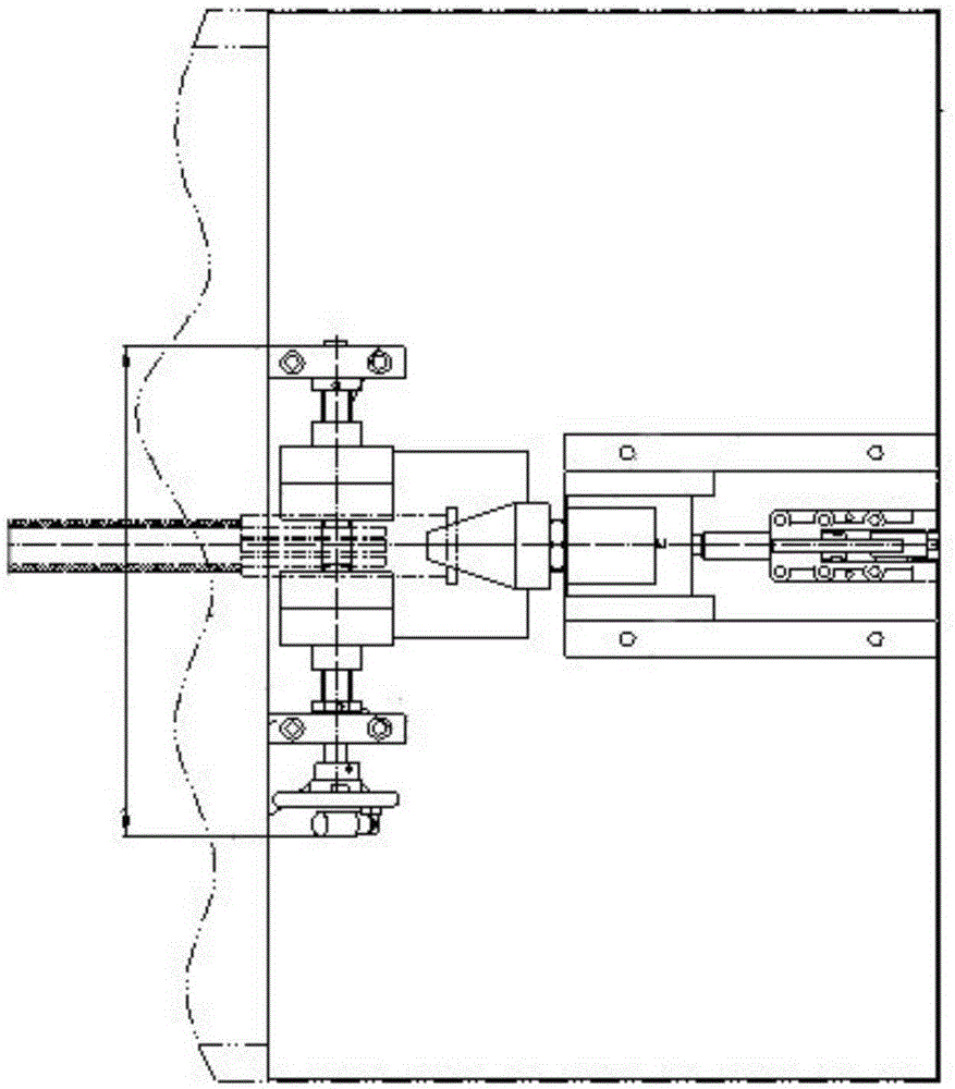
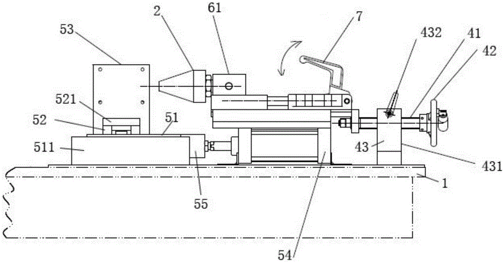
[0023] refer to Figure 3 ~ Figure 5 , the quick clamping device of the pipeline cleaning machine in this embodiment includes a base plate 1, a nozzle 2, a pipe fitting 3, a pipe fitting clamping assembly, a nozzle sliding assembly and a quick clamp 7, a pipe fitting clamping assembly is arranged on the bottom plate, and the pipe fitting clamping A pipe fitting 3 is arranged on the assembly, and a nozzle 2 is arranged on one side of the pipe fitting clamping assembly, and the nozzle 2 is fixed on the nozzle sliding group, and also includes a nozzle adjustment assembly and a clamp sliding assembly, and the nozzle adjustment assembly includes an adjustment screw 41 and adjustment Hand wheel 42, the clamp slide assembly includes clamp slide 81 and clamp slide rail 82, the quick clamp 5 and nozzle slide assembly are installed on the clamp slide 81, clamp slide 81 is installed on In the clamp slide rail 82 , one end of the adjusting screw rod 41 is fixedly connected with the clamp ...


PUM


Abstract

The invention discloses a rapid clamping device for a pipeline cleaning machine. The rapid clamping device for the pipeline cleaning machine comprises a base plate, a nozzle, a pipe, a pipe clamping assembly, a nozzle sliding assembly and a rapid clamp. The pipe clamping assembly is arranged on the base plate. The pipe is arranged on the pipe clamping assembly. The nozzle is arranged on one side of the pipe clamping assembly and connected with the nozzle sliding assembly. The rapid clamping device for the pipeline cleaning machine further comprises a nozzle adjustment assembly and a clamp sliding assembly. The nozzle adjustment assembly comprises an adjustment lead screw and an adjustment hand wheel. The clamp sliding assembly comprises a clamp sliding block and a clamp sliding rail. The rapid clamp and the nozzle sliding assembly are both installed on the clamp sliding block. The clamp sliding block is installed in the clamp sliding rail. One end of the adjustment lead screw is fixedly connected with the clamp sliding block, and the other end of the adjustment lead screw is provided with the adjustment hand wheel. The rapid clamping device is mainly used for rapidly clamping and locking a connector of a rubber pipe or a hard pipe on the pipeline cleaning machine.

Description

technical field [0001] The invention relates to a quick clamping device, in particular to a quick clamping device for a pipeline cleaning machine. Background technique [0002] At present, there are mainly two types of quick clamping devices used for cleaning machines on the market. The first is the clamping mode of the cylinder and the thread, and the second is the clamping mode of positive and negative threads. [0003] see figure 1 , the first way is the way the cylinder is clamped with the thread. Its specific structure is to adopt the cylinder to cooperate with thread clamping, and there is no nozzle adjustment component. The advantage of this structure is that it is relatively simple and takes up relatively little space. The disadvantages are: first, the adjustment of the lead screw is time-consuming and laborious. For different types of pipe fittings, especially those with a relatively large diameter difference, the screw needs to be turned during the switching op...

Claims


Application Information

Patent Timeline
Patent Type & Authority Applications(China)
IPC IPC(8): B08B9/032B08B13/00
CPCB08B9/032B08B13/00B08B2209/032
Inventor 刘传喜吕峥
Owner 全加机械设备(上海)有限公司
Learn More