
Rotary drilling processing control system of cylinder cover of diesel engine

A control system and cylinder head technology, applied in metal processing, boring/drilling, automatic control devices, etc., can solve problems such as time-consuming and labor-intensive, affecting the machining accuracy and position accuracy of each hole, and affecting the performance of the diesel engine

Active Publication Date: 2016-03-16
全椒县新华机械有限责任公司
View PDF8 Cites 8 Cited by
  • Summary
  • Abstract
  • Description
  • Claims
  • Application Information

AI Technical Summary

Problems solved by technology

[0002] The cylinder head is one of the important parts of the diesel engine. The holes on the cylinder head involve multi-faceted holes. At present, when the holes on the cylinder head are processed, the cylinder head has a first surface and a second surface. The first surface and the second surface are set opposite to each other. Both the first and second sides of the cover have the first position hole and the second position hole. The drilling jig can only be processed on one of the positions on one of the sides once clamped on the same machine tool, and it needs to be replaced by Drilling molds can complete the processing of the first position hole and the second position hole on each surface of the cylinder head, and when processing the holes on different surfaces, the cylinder head needs to be turned over, which is time-consuming and labor-intensive. Not only the work efficiency is low, but the processing cost High, and multiple clamping affects the machining accuracy and position accuracy between the holes, thus affecting the overall performance of the diesel engine

Method used


Image

  • Rotary drilling processing control system of cylinder cover of diesel engine
  • Rotary drilling processing control system of cylinder cover of diesel engine
  • Rotary drilling processing control system of cylinder cover of diesel engine

Examples


Embodiment Construction

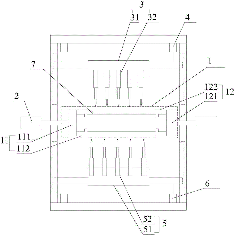
[0019] refer to figure 1 , figure 2 , image 3 , the present invention proposes a diesel engine cylinder head rotary drilling processing control system, including a cylinder head fixing device 1, a first driving device 2, a first drilling device 3, a second driving device 4, a second drilling device 5, a second Three driving devices 6, a first distance measuring sensor, a second distance measuring sensor and a control device, wherein:

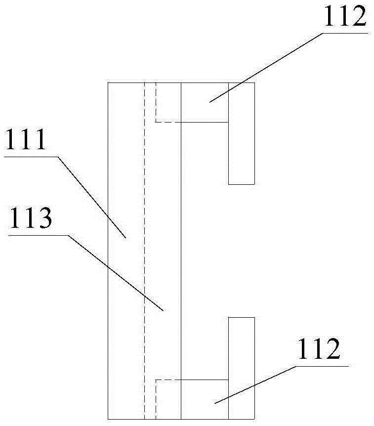
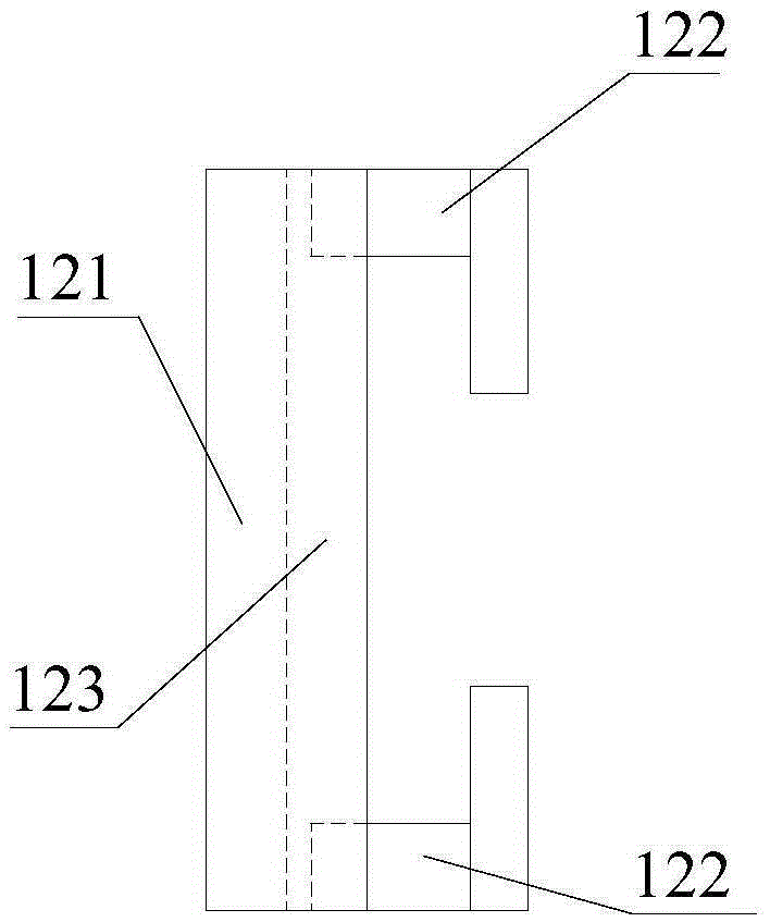
[0020] The cylinder head fixing device 1 is used for fixing the cylinder head 7 . The cylinder head fixing device 1 includes a first fixing unit 11 and a second fixing unit 12 arranged side by side along the horizontal direction. As for the fixing part, the cylinder head 7 is axially fixed by cooperating with the first fixing part on the first fixing unit 11 and the second fixing part on the second fixing unit 12 . The first fixing unit 11 also includes a first base 111, the first fixing part includes two first clamping heads 112, the two ...


PUM


Abstract

The invention provides a rotary drilling processing control system of a cylinder cover of a diesel engine. The system comprises a cylinder cover fixing device, a first drilling device, a second drilling device, a first driving devices, second driving devices, third driving devices, a first ranging sensor, a second ranging sensor and a control device, wherein the cylinder cover fixing device is used for fixing the cylinder cover; the first driving devices are used for driving the cylinder cover fixing device to rotate; the first drilling device is used for processing first position holes in a first surface and a second surface of the cylinder cover; the second driving devices are connected to the first drilling device and used for driving the first drilling device to vertically move up and down on the corresponding first position hole; the second drilling device is used for processing second position holes in the first surface and the second surface of the cylinder cover; the third driving devices are used for driving the second drilling device to vertically move up and down below the corresponding second position hole. The system is simple in structure and can automatically drill the cylinder cover of the diesel engine.

Description

technical field [0001] The invention relates to the technical field of diesel engine cylinder head production and processing, in particular to a diesel engine cylinder head rotary drilling processing control system. Background technique [0002] The cylinder head is one of the important parts of the diesel engine. The holes on the cylinder head involve multi-faceted holes. At present, when the holes on the cylinder head are processed, the cylinder head has a first surface and a second surface. The first surface and the second surface are set opposite to each other. Both the first and second sides of the cover have the first position hole and the second position hole. The drilling jig can only be processed on one of the positions on one of the sides once clamped on the same machine tool, and it needs to be replaced by Drilling molds can complete the processing of the first position hole and the second position hole on each surface of the cylinder head, and when processing the...

Claims


Application Information

Patent Timeline
IPC IPC(8): B23B41/00B23B39/22B23B47/26B23Q3/06B23Q7/00B23Q15/14
CPCB23B39/22B23B41/00B23B47/26B23Q3/062B23Q7/00B23Q15/14
Inventor 王臣
Owner 全椒县新华机械有限责任公司
Learn More