
An electronic product assembly line

A technology for assembling production lines and electronic products, applied in assembly machines, metal processing equipment, manufacturing tools, etc., can solve the problems of difficult line, low efficiency, large site area, etc., to achieve flexible adaptability, improve transmission accuracy, The effect of preventing the belt from slipping

Active Publication Date: 2018-01-23
深圳橙子自动化有限公司
View PDF8 Cites 0 Cited by
  • Summary
  • Abstract
  • Description
  • Claims
  • Application Information

AI Technical Summary

Problems solved by technology

[0002] In the prior art, the assembly line used by the factory realizes product transfer through manual assembly. This kind of equipment is mainly belt line and drum line, and generally includes double-speed chain, tooling plate, stop mechanism, jacking and traversing, and electric control system. , three-phase motor, etc., in the production process, it only plays the role of conveying the product, and cannot realize accurate positioning, and then has the following defects: First, it cannot realize the precise positioning of the product in the conveying process, because the transmission of the belt can cause the belt and The product is slipping, and at the same time, the frequency conversion control cannot be used to achieve precise stop after the product is in place; secondly, the connection between the automation equipment and the production line cannot be realized. requirements, the traditional belt line cannot meet the above requirements; thirdly, due to the different process requirements for the assembly of electronic products, there are certain requirements for the flexibility and adaptability of the production line. Because the belt line is relatively heavy, it is difficult to change the line once it is put into production; at the same time , because the belt line cannot turn at a small angle, so the equipment has a large area for the site; in addition, because the belt line cannot achieve accurate positioning of the transmission, it needs fixtures to assist secondary positioning during the assembly process, which is not efficient

Method used


Image

  • An electronic product assembly line
  • An electronic product assembly line
  • An electronic product assembly line

Examples


Embodiment Construction

[0021] The present invention will be described in more detail below in conjunction with the accompanying drawings and embodiments.

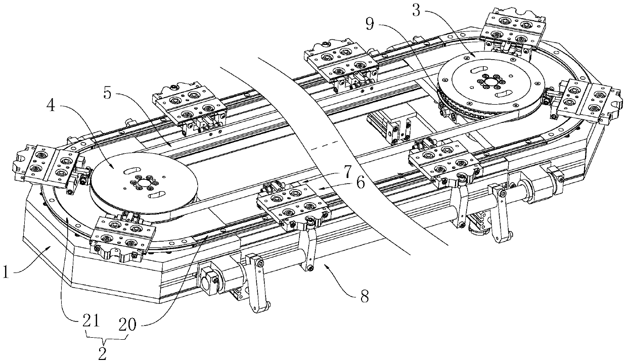
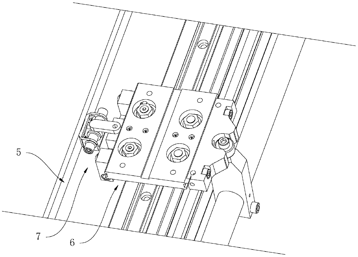
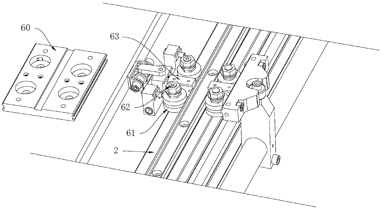
[0022] The invention discloses an electronic product assembly production line, which combines Figure 1 to Figure 7 As shown, it includes a frame 1, and the frame 1 is provided with a slide rail 2, and the slide rail 2 includes two linear guide rails 20 and two arc guide rails 21, and the two linear guide rails 20 are arranged in parallel, Two arc guide rails 21 are separately arranged at two ends of two linear guide rails 20 so that the slide rail 2 is in the shape of a racetrack. The inside of the slide rail 2 is provided with a driving wheel 3 and a driven wheel 4, and the driving wheel 3 and the driven wheel 4 is connected by a belt 5, and a preset distance is maintained between the belt 5 and the slide rail 2, and a plurality of slider assemblies 6 are arranged on the slide rail 2, and the slider assemblies 6 and the belt 5 pass through a lo...


PUM


Abstract

The invention discloses an assembly production line of electronic products. The assembly production line comprises a frame, wherein a sliding rail is arranged on the frame and comprises two straight guide rails and two arc guide rails; the two straight guide rails are arranged in parallel, and the two arc guide rails are respectively arranged at two ends of the two straight guide rails, so that the sliding rail is in the shape of a racetrack; a driving wheel and a driven wheel are arranged on the inner side of the sliding rail, and are connected through a belt; a preset distance is maintained between the belt and the sliding rail, and a plurality of sliding block assemblies are arranged on the sliding rail; the sliding block assemblies are connected with the belt through lock catch assemblies; positioning assemblies are arranged outside the straight guide rails and on the frame, and are used for locking or releasing the sliding block assemblies moving to the straight guide rails. The assembly production line disclosed by the invention obtains the beneficial effects that belt creep is avoided, conveying loads are reduced, conveying precision is improved, and flexible adaptability is obtained.

Description

technical field [0001] The invention relates to a production line, in particular to an electronic product assembly production line. Background technique [0002] In the prior art, the assembly line used by the factory realizes product transfer through manual assembly. This kind of equipment is mainly belt line and drum line, and generally includes double-speed chain, tooling plate, stop mechanism, jacking and traversing, and electric control system. , three-phase motor, etc., in the production process, it only plays the role of conveying the product, and cannot realize accurate positioning, and then has the following defects: First, it cannot realize the precise positioning of the product in the conveying process, because the transmission of the belt can cause the belt and The product is slipping, and at the same time, the frequency conversion control cannot be used to achieve precise stop after the product is in place; secondly, the connection between the automation equipme...

Claims


Application Information

Patent Timeline
Patent Type & Authority Patents(China)
IPC IPC(8): B23P21/00
CPCB23P21/00
Inventor 邵勇锋
Owner 深圳橙子自动化有限公司
Learn More