
Cooling device for variable propeller cabinet and wind power generation unit

A cooling device and pitch cabinet technology, which is applied in wind turbines, wind power generation, engines, etc., can solve the problems of inability to cool the pitch cabinet, affect the cooling effect of the pitch cabinet, and limit the heat dissipation effect, so as to improve reliability and service life, improved availability, and high reliability

Active Publication Date: 2016-03-16
BEIJING GOLDWIND SCI & CREATION WINDPOWER EQUIP CO LTD
View PDF14 Cites 4 Cited by
  • Summary
  • Abstract
  • Description
  • Claims
  • Application Information

AI Technical Summary

Problems solved by technology

However, the forced air cooling of the pitch cabinet has the disadvantages of affecting the cooling effect of the pitch cabinet due to factors such as uncontrollable air volume and wind pressure. , the air inside this space can only circulate in this narrow space, and the heat dissipation effect is limited. Moreover, due to the existence of the heat source of the pitch control cabinet, the air temperature in this part continues to rise, so the cooling method of forced air cooling is adopted here It has little effect and cannot achieve the purpose of cooling the pitch cabinet

Method used


Image

  • Cooling device for variable propeller cabinet and wind power generation unit
  • Cooling device for variable propeller cabinet and wind power generation unit
  • Cooling device for variable propeller cabinet and wind power generation unit

Examples


Embodiment 1

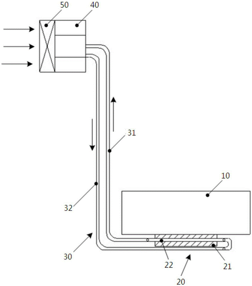
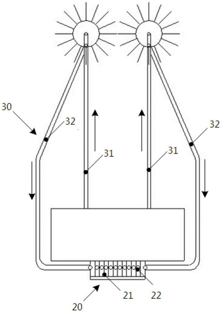
[0032] The following first introduces the pitch cabinet cooling device of the embodiment of the present invention, figure 1 It is a schematic front view of the structure of the pitch cabinet cooling device in this embodiment; figure 2 for figure 1 right view of .

[0033] Such as figure 1 As shown, the pitch cabinet cooling device in the embodiment of the present invention mainly includes a heat collector 20, a condenser 40, and a pipeline 30 arranged between the heat collector 20 and the condenser 40. The pipeline 30 includes a gas collector 31 and a The liquid return pipe 32 and the pipeline 30 form a loop between the heat collector 20 and the condenser 40, and the loop is filled with cooling medium.

[0034] Such as figure 2 As shown, both the air collecting pipe 31 and the liquid return pipe 32 have a double-pipe structure, and this double-pipe structure can make the cooling medium flow more fully in the circuit, so that the cooling effect is better. In order to enh...

Embodiment 2

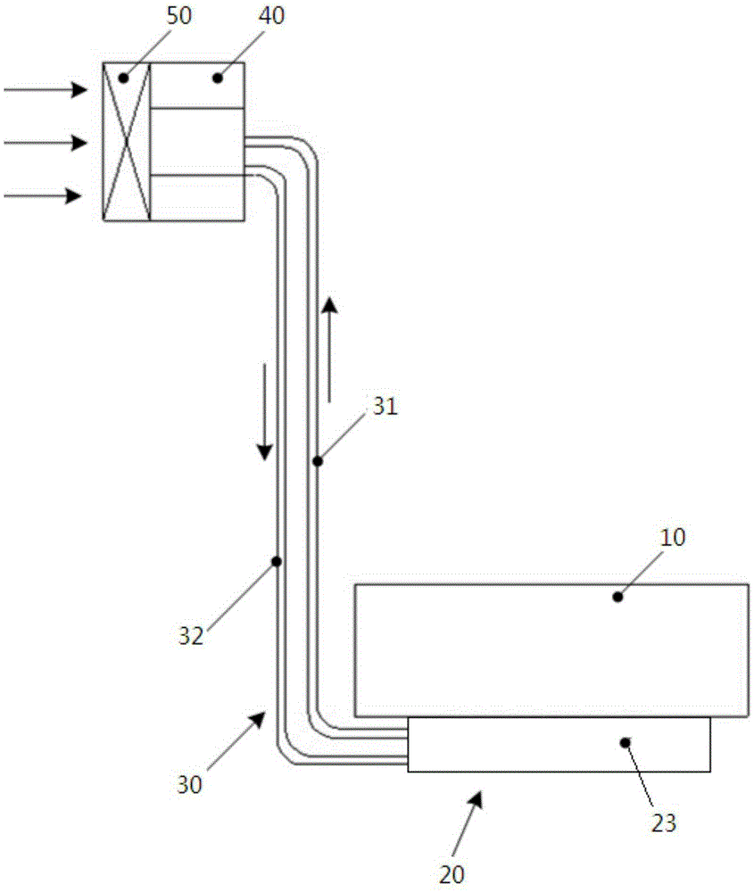
[0040] Such as image 3 , Figure 4 As shown, the difference between this embodiment and the first embodiment lies in that the structure of the heat collecting device 20 is different.

[0041] In this example, the heat collecting device 20 is a heat collecting box 23 tightly attached to the heating part of the pitch cabinet 10, and the heat collecting box 23 is a box structure, and of course it can also be in other shapes such as a cylinder, as long as it can be realized The effective heat transfer of the pitch cabinet 10 and the vaporization of the cooling device filled in the pitch cabinet 10 are enough. Through contact with the pitch cabinet 10 , the heat of the pitch cabinet 10 is transferred to the heat collection box 23 . The heat collection box 23 forms a loop with the condenser 40 through a pipeline 30 , wherein the pipeline 30 includes a gas collector 31 and a liquid return pipe 32 . At the same time, a Pt100 temperature sensor is also installed on the contact surf...

Embodiment 3

[0046] The following describes the wind power generating set including the cooling device for the above-mentioned pitch cabinet.

[0047] Figure 5 It is a schematic diagram of a wind power generating set with a pitch cabinet cooling device disclosed in an embodiment of the present invention, including a tower 5, and above the tower 5, a nacelle 4, a generator 3, an impeller 2, and a shroud 1 are arranged. The structures are all prior art, and will not be repeated here.

[0048] Such as Figure 6 As shown, the pitch cabinet 10 is arranged in the narrow space formed by the hub 6 of the impeller 2 and the main shaft 7. In this embodiment, in order to achieve a better cooling effect for the pitch cabinet cooling device, the heat collector 20 is set In the heating part of the pitch cabinet 10, the condenser 40 and the fan 50 are arranged in the large-space low-temperature area in the shroud 1, and the heat collecting device 20 and the condenser 40 are connected by a pipeline 30 ...


PUM


Abstract

The invention provides a cooling device for a variable propeller cabinet and a wind power generation unit. The cooling device for the variable propeller cabinet comprises a heat collection device and a condenser, wherein the heat collection device is arranged at the heating part of the variable propeller cabinet and is communicated with the condenser through a pipeline to form a loop; and a cooling medium is arranged in the loop, vaporizes through absorbing heat in the heat collection device, is liquefied through releasing the heat in the condenser and carries out circulation movement in the loop. According to the technical scheme provided by the invention, the problem about over temperature of the variable propeller cabinet is effectively solved, so that the wind power generation unit cannot shut down due to over temperature of the variable propeller cabinet, and the availability and the whole machine income of the wind power generation unit are increased; and the whole body of the variable propeller cabinet is ensured to be at lower temperature, so that a good working environment is provided for an electric element in a cabinet body, the reliability of the electric element is improved, and the service life of the electric element is prolonged. The cooling device has a simple structure, is convenient in installation and has higher reliability and longer service life.

Description

technical field [0001] The invention relates to the technical field of wind power generation, in particular to a pitch cabinet cooling device and a wind power generating set. Background technique [0002] The pitch system is an important part of the variable speed and pitch wind turbine. It realizes the stable output of the wind turbine power by adjusting the pitch angle of the blades when the wind turbine is above the rated wind speed. The safe operation of the generator set plays a vital role, so the stable operation and maintenance of the pitch system is an important guarantee for the continuous output of wind turbine power. [0003] The electronic control devices in the pitch system will generate heat during operation, which needs to be dissipated to ensure the normal operation of the pitch system. As the shell of the pitch system, the pitch cabinet is generally installed in the impeller hub of the wind turbine, and the impeller hub is generally a relatively closed stru...

Claims


Application Information

Patent Timeline
Patent Type & Authority Applications(China)
IPC IPC(8): F03D80/60
CPCY02E10/72
Inventor 高杨白洛林方涛
Owner BEIJING GOLDWIND SCI & CREATION WINDPOWER EQUIP CO LTD
Learn More