
Testing mechanism used for testing main pin positioning angle during dynamic driving of vehicle

A technology of positioning angle and testing mechanism, which can be used in measuring devices, instruments, optical devices, etc., and can solve problems such as lack of wheel positioning parameter testing.

Inactive Publication Date: 2016-03-16
WANXIANGQIANCHAO CO LTD +1
View PDF5 Cites 2 Cited by
  • Summary
  • Abstract
  • Description
  • Claims
  • Application Information

AI Technical Summary

Problems solved by technology

[0003] The general test of the toe-in and camber angle of the car is carried out by four-wheel alignment and other instruments when the vehicle is statically stopped, and there is a lack of a mechanism that can test the wheel alignment parameters during the dynamic driving process of the vehicle.

Method used


Image

  • Testing mechanism used for testing main pin positioning angle during dynamic driving of vehicle
  • Testing mechanism used for testing main pin positioning angle during dynamic driving of vehicle
  • Testing mechanism used for testing main pin positioning angle during dynamic driving of vehicle

Examples


Embodiment Construction

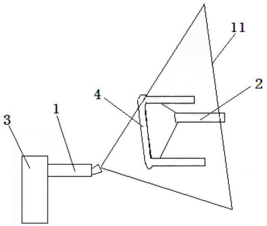
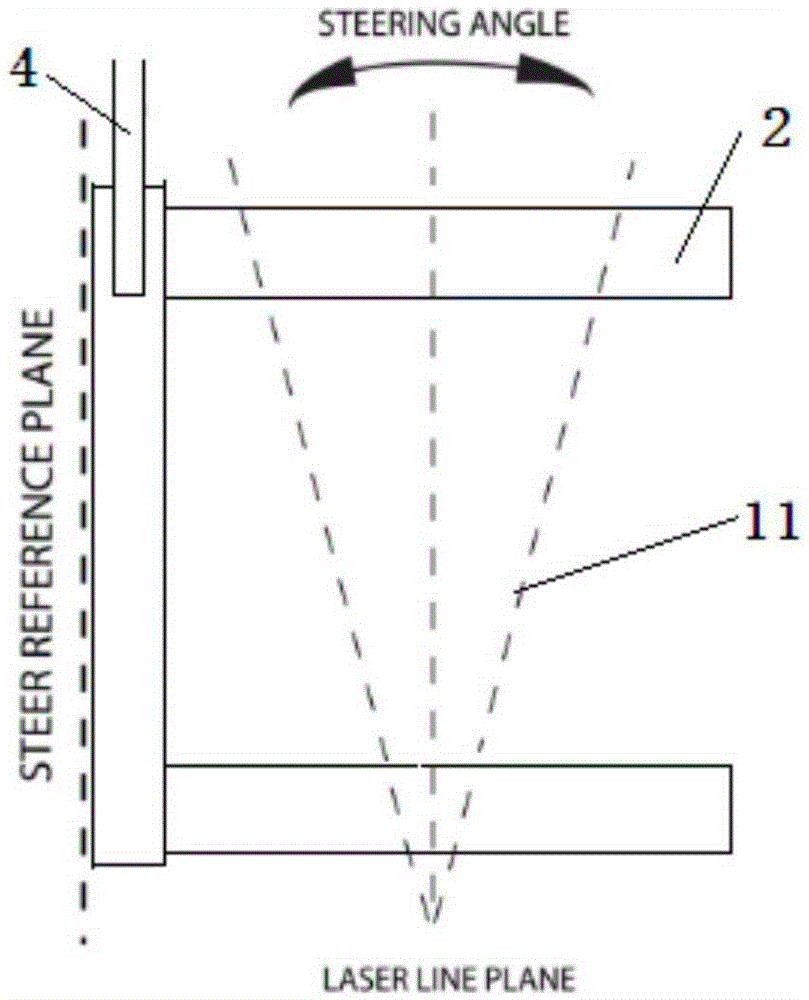
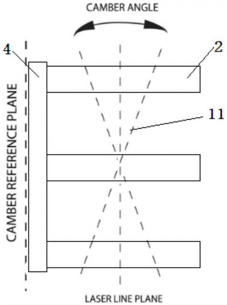
[0012] The present invention will be described in detail below in conjunction with accompanying drawing: figure 1 As shown, the present invention includes a laser transmitter 1, a laser induction column 2, and a wheel 3. The laser transmitter 1 is fixed on the outer center of the wheel 3, and the laser induction column 2 is provided with three, and is fixed on the vehicle body 4 above; the vehicle body surface where the laser sensor column 2 is located is on the same side as the wheel 3 where the laser transmitter 1 is located, and the vehicle body surface is the vehicle body edge of the wheel 3; the laser projection plane 11 projected by the laser transmitter 1 On the three laser sensing columns 2 on the vehicle body 4; the three laser sensing columns 2 are distributed in an equilateral triangle shape, that is, the distance between each laser sensing column 2 is equal.

[0013] The present invention can project the laser projection plane 11 sent by the laser emitter 1 to thre...


PUM


Abstract

The invention relates to a testing mechanism used for testing a main pin positioning angle during dynamic driving of a vehicle. The testing mechanism comprises a laser transmission device, three laser induction columns, and a vehicle wheel. The laser transmission device is fixedly disposed on the center of the outer side of the wheel. The three laser induction columns are fixedly disposed on the vehicle body. The side surface of the vehicle provided with the laser induction columns and the wheel provided with the laser transmission device are the same side, and the side surface of the vehicle is the side edge of the vehicle body of the wheel. The laser transmitted by the laser transmission device is projected on the three laser induction columns on the vehicle body, and the three laser induction columns are in the shape of an equilateral triangle. The testing mechanism is advantageous in that the changing states of the wheel toe-in and the camber angle with respect to the vehicle body during the dynamic driving of the vehicle can be tested by adopting the optical principle and the triangle relation via the laser projection, and the important reference can be provided for the development of the kinematics of the suspension system and the toe-in camber positioning development of the vehicle.

Description

technical field [0001] The invention belongs to the technical field of a testing mechanism for testing a kingpin positioning angle, in particular to a testing mechanism for testing a kingpin positioning angle during dynamic running of a vehicle. Background technique [0002] The toe-in and camber angles of the car are important factors that affect the driving stability and comfort of the car, as well as tire wear. [0003] The general test of the toe-in and camber angle of the car is carried out through four-wheel alignment and other instruments when the vehicle is statically stopped, and there is a lack of a mechanism that can test the wheel alignment parameters during the dynamic driving process of the vehicle. Contents of the invention [0004] The purpose of the present invention is to overcome the deficiencies in the prior art, and provide a test mechanism for testing the kingpin positioning angle in the dynamic running of the vehicle, which can be used to test the re...

Claims


Application Information

Patent Timeline
Patent Type & Authority Applications(China)
IPC IPC(8): G01B11/26
CPCG01B11/26
Inventor 邱宝象资小林郭增均张杰石伯妹林光钟
Owner WANXIANGQIANCHAO CO LTD
Learn More