
An Auxiliary Sampling Circuit of Primary Inductance Peak Current of Switching Power Supply

A technology of sampling circuit and switching power supply, which is applied in the direction of AC/pulse peak measurement, etc., and can solve problems such as internal calculation errors and performance degradation of controller chips

Active Publication Date: 2018-02-06
成都启臣微电子股份有限公司
View PDF5 Cites 0 Cited by
  • Summary
  • Abstract
  • Description
  • Claims
  • Application Information

AI Technical Summary

Problems solved by technology

However, due to unpredictable factors such as transmission delay inside the switching power supply controller chip, there is a time delay between the PWM signal being turned off and the BD port of the switching power supply controller chip being actually turned off. During the actual shutdown process of the BD port, the primary peak voltage of the switching power supply continues to rise, resulting in a deviation between the sampled primary peak voltage of the switching power supply and the real peak voltage of the switching power supply, which in turn causes the sampled value of the peak current of the primary inductor of the switching power supply to be different from the real value. There is a deviation between them, so that there is an error in the internal operation, which will lead to a decrease in the overall performance of the controller chip

Method used


Image

  • An Auxiliary Sampling Circuit of Primary Inductance Peak Current of Switching Power Supply
  • An Auxiliary Sampling Circuit of Primary Inductance Peak Current of Switching Power Supply
  • An Auxiliary Sampling Circuit of Primary Inductance Peak Current of Switching Power Supply

Examples


Embodiment 1

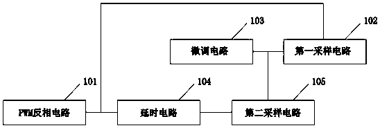
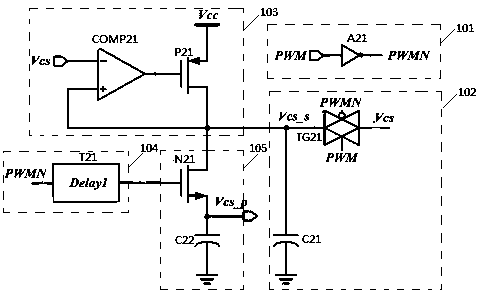
[0024] Please refer to figure 1 , 2 as shown, figure 1 The structural block diagram of the switching power supply primary inductor peak current auxiliary sampling circuit provided by the embodiment of the present invention. figure 2 The schematic diagram of the circuit structure of the peak current auxiliary sampling circuit of the primary inductance of the switching power supply provided by the embodiment of the present invention.

[0025] In this embodiment, the switching power supply primary inductor peak current auxiliary sampling circuit includes a PWM inverting circuit 101 , a first sampling circuit 102 , a trimming circuit 103 , a delay circuit 104 and a second sampling circuit 105 .

[0026] The PWM inverting circuit 101 includes a NOT gate A21, the input terminal of the NOT gate A21 is externally connected to the PWM signal output by the control unit of the switching power supply, and the output terminal is connected to the first sampling circuit 102 and the delay ...


PUM


Abstract

Disclosed in the invention is an auxiliary sampling circuit of a primary inductance peak current of a switching power supply. The auxiliary sampling circuit is composed of a PWM inverting circuit, a first sampling circuit, a fine tuning circuit, a delay circuit and a second sampling circuit. The fine tuning circuit carries out fine tuning on a first sampling voltage obtained by the first sampling circuit and compensating for an error caused by delayed internal transmission of a power controller chip. The delay circuit enables the internal transmission delay of the power controller chip to be completed when the second sampling circuit starts to carry out sampling and guarantees that a final sampling voltage of the second sampling circuit is a switching power supply primary peak voltage reaching a peak value, thereby realizing sampling of the actual primary peak voltage of the switching power supply. For the primary peak voltage, the precise switching power supply primary inductance peak current can be obtained by a sampling resistor, thereby avoiding inaccuracy of primary inductance peak current sampling of the switching power supply due to factors like transmission delay and the like. The sampling precision is guaranteed; and stability and consistency of the switching power supply controller chip are improved.

Description

technical field [0001] The invention relates to the technical field of electronic circuits, in particular to an auxiliary sampling circuit for the peak current of the primary inductance of a switching power supply. Background technique [0002] With the rapid development of integrated circuits, switching power supplies are being used more and more as an indispensable part of the integrated circuit field. As an important technical parameter of switching power supply, the peak current of the primary inductor of switching power supply will greatly affect its sampling accuracy. The overall performance of the switching power supply controller chip. The traditional sampling circuit samples the peak current of the primary inductor of the switching power supply when the PWM signal is turned off. However, due to unpredictable factors such as transmission delay inside the switching power supply controller chip, there is a time delay between the PWM signal being turned off and the BD ...

Claims


Application Information

Patent Timeline
Patent Type & Authority Patents(China)
IPC IPC(8): G01R19/04
CPCG01R19/04
Inventor 马强向磊吴强许刚颍唐波
Owner 成都启臣微电子股份有限公司
Learn More